

Article by Christoph Nüssel
___
Furthermore, it is important to keep in mind that the gasket itself cannot be considered as “tight” but only the whole sealing system consisting of bolts, hardened washer, flanges and gasket – can be called technically tight or not.
Keeping that in mind, the expression “tightness” has several meanings. For instance, a tire of a car is sufficiently tight when the internal pressure stays nearly constant for one month. After this period of time it can be refilled to the foreseen level again without causing any trouble. If the tire has to be inflated daily, the leakage rate is too high and this system would not be considered tight. Another example are LED-spotlights for outdoor applications. They could be defined as tight, if no water enters the inner part of the housing after a complete immersion of the product at defined conditions.
What means tight in bolted connections? The problem is that we usually cannot visibly detect a leakage, for example of a gaseous medium. The tightness of connections is classified in leakage classes Lx.x, which are usually determined in laboratory testing. For instance, the tightness class L0.1 stands for a leakage rate of 0.1 mg/(s*m). This physical unit represents a loss of mass per time in relation to the gasket’s circumference. That means that a larger connection like a DN 400 PN 16 has a higher loss of medium in the same time frame against a smaller flange i.e DN 40 PN 16 connection with the same defined leakage class.
This description of leakage is very abstract at first view. To make it more clear an example calculation will follow. For a raised face flange connection PN 40 DN 40 the standard gasket size is 49 x 92 mm. The compressed area of the gasket is 49 x 88 mm due to the sealing face’s raised geometry. The gasket size is taken into account with the middle compressed circumference of the gasket ring – (49+88)/2*π = 215 mm in this case.
Big potential in reduction
The gas leakage in volume at 20 °C for this connection is shown with different leakage classes in the diagram below.
The calculations’ result for leakage class L1.0 is a loss of medium of 463 l per month. The following tightness classes are then ten times tighter. Thus, the loss of medium with class L0.1 is 46.3 l per month and further on. In the diagram there is a huge difference between L1.0 and L0.1 and a much smaller one between the following leakage classes. Between L0.01 and L0.001 there is nearly no difference visible anymore.
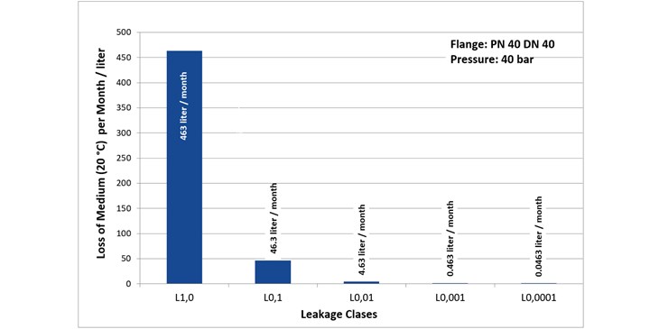
Summing up the data from the diagram, it makes not too much sense to discuss about leakage rates of L0.001 or lower. But it is worth it to reduce leakage rates down to L0.01, because that means a huge reduction of diffuse emissions and loss of medium.
Practical sealing applications
But how can we use this information in practical sealing applications? For example, there is a technical standard for nuclear power plants in Germany called KTA 3211.2. In this document there is an allocation of tightness classes for applications. The class L1.0 is used for water pipes. L0.1 is applied in steam pipes and L0.01 is used for systems with radioactive steam. This graduation shows that liquids are easier to seal than gaseous media. Furthermore, the requirements on tightness are higher for critical media.
Another example, which is used especially in the chemical industry in Germany, is the leakage criterion of VDI 2290 related to the German clean air act (coming soon revision of TA Luft). It says that “according to the state of the art, flange joints are technically tight (…) if (…) the specific leakage rate ≤ 0.01 mg/(s*m) is applied (…).2 This standard defines a technical tightness, which fulfills the state of the art requirements.
How flat gaskets work
A precondition for an adequately working connection is a state of the art gasket material. Provided that the sealing system’s components are suitable for the medium (chemical resistance) and for the temperature (temperature resistance) in the application, there is one parameter left that is also important for the quality of the connection: the installed level of gasket surface pressure.
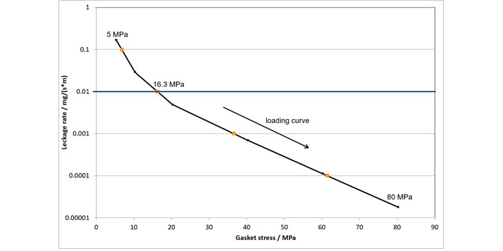
The above diagram shows the influence of surface pressure on the tightness of a connection with a flat gasket. The curve is measured with 25 bar internal pressure of helium and with a PN 40 DN 40 gasket ring. The image shows the loading curve of the gasket. This curve is equal to the situation at assembly. The surface pressure is step-wise increased – starting from 5 MPa up to 80 MPa. At assembly, the leakage at 5 MPa is 1.6*10-1 mg/(s*m).
With increasing surface pressure the leakage rate of the connection decreases, down to nearly 1.8*10-5 mg/(s*m) at 80 MPa. Assuming that the leakage rate of the connection should be a maximum 10-2 mg/(s*m) to reach technical tightness, a surface pressure of 16.3 MPa on the gasket is necessary. This however is only the situation at assembly, during service losses of stress due to heat/pressure effects the leakage rate. The EN1591-1 calculations take these effects into account to ensure the connection remains technically tight. Maintaining the connection as technically tight can be complicated and requires a whole new article.
1Tietze – Handbuch Dichtungspraxis 2. Auflage
About ESA
Established in 1992, the European Sealing Association (ESA) is registered in Neu-Ulm (D) as a non-profit trade association, representing the manufacturers and suppliers of sealing devices and materials. The Members of the ESA represent a strong majority of the sealing industry in Europe.