

Auxiliary valves (Axy) are needed to conduct in-service maintenance and repair on pressurized gate or ball valves in a safe manner. Axy valves should be used in combination with service valve for throttling. This is part 1 of the article, the second part will be published in Valve World September.
By Ingolf Holmslet
Axy valve™ is an auxiliary valve installed in the cavity of a gate or a ball valve, with the purpose of controlling, testing, setting barrier or performing maintenance on the main valve. iSmart™ (in-service maintenance and repair technology) is service, maintenance, on gate or ball valves performed in line under pressure.
To perform iSmart, you need Axy valves installed in the cavity vent or cavity drain on the main valve. All parallel gate, large wedge gate and ball valves will be equipped with a blind or a bleed plug in the cavity.
One can ask, what is the purpose of a blind or a bleed plug? And the answer is, to plug off the hole or to bleed out of the cavity when the valve is without pressure. Some claim that a bleed plug, or a grease fitting can be used to drain the valve cavity. In most cases this is not correct.
It is not only not correct, but it could also be dangerous. In the worst case, people could get seriously hurt.
Not Safe
Let me explain. You would never open a blind plug with pressure on the inside of the plug. On most bleed plugs the bleed hole is small and if opening with high pressure gas on the inside, you risk hydrate plugging the bleed hole. If you try to bleed through the bottom bleed plug, you may have a clogged bleed plug, giving you the wrong idea that there is no pressure on the inside. If you open a bleed plug under pressure, you may also risk that you are unable to close off the bleed plug.
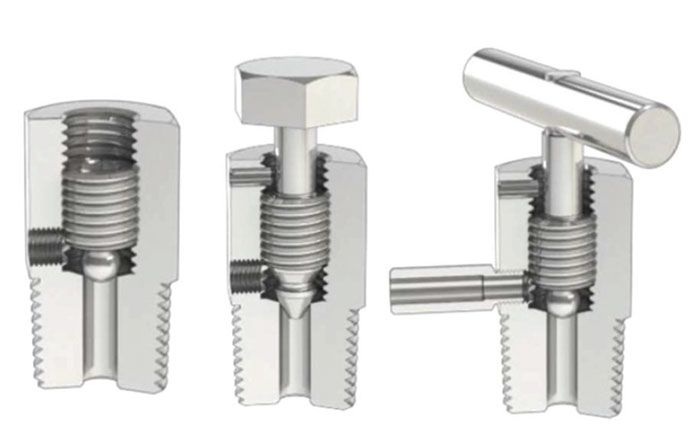
Bleed plugs are available in several configurations. Figure 1 shows three different types with two different outlets. Some bleed plugs have a small outlet (2-4 mm). Others can go up to 8-10 mm but these are not safe for use under pressure.
I would never recommend using a bleed plug in pressurized conditions as you cannot trust them.
Two valves
Therefore, it is important to install Axy valves in the cavity. An Axy valve consists of:
* an inlet connection, this can be RTJ flange (as in Figure 2), compact flange or NPT threads as per the users preference.
- A body, floating ball (tungsten-carbide {TC} coated) with 12 mm bore with two floating seats (TC coated) with radial seals, and a handle that can be taken off to prevent accidental operation of the valve.
An outlet, one 1⁄4” NPT for connecting the gauge, one ∞” NPT for connecting the service valve and in some cases two ∞” NPT for an additional connection for TRV (thermic relief valve) on DIB-1 valves.
The Axy valve system consist of two valves: The Axy valve and the service valve. The Axy valve is an on/off valve, and the service valve is a throttling valve. There are several different valve configurations all depending on the installation space available. The valve illustrated in Figure 4 can be as short as 120 mm with both the outlet for the gauge and the service valve on the side of the valve making it easy to install and use.

Difference between modular and Axy valves?
The question arises, what is the difference between a modular valve and the Axy system? Consider the wedge gate modular valve shown in Figure 3. Whilst there is nothing inherently wrong with this valve, it is important to be aware that the construction can result in several disadvantages.
1) The modular valve consists of two block valves and a bleed valve in one body. That makes the valve relatively large. Due to this the valve needs a lot of space for installation.
2) It becomes quite heavy and if the connection to the main valve is NPT threads it is a lot of weight on those threads. If that valve should be installed into threads, it would need extra supporting.
3) When using the modular valve, the inner valve will be opened first to protect it. When using valve number two as a throttling valve that valve will in all probability start to leak at a given moment. To repair the modular valve, you must shut down to replace it or replace the whole modular valve.

Cramped places
The Axy valve will never be used to throttle and will be protected against erosion or cavitation. All throttling will be done with the service valve installed to the outlet of the Axy valve Figure 5. After use, the service valve and the gauge will be taken off the Axy valve and replaced with the blind and the bleed plug. If the service valve starts to leak due to wear on the ball / seats, it will be repaired or replaced with a new valve all without having to shut down.
Under normal conditions the Axy valve will be installed without a handle and with a bleed plug in the service port (1/2”) and a blind plug in the gauge port (as in Figure 4). When you need to work with the Axy valve you control that the valve is in the closed position. Open the bleed plug to control that the Axy ball is sealed. Then take out the 1⁄4” blind plug and install the gauge. Take out the bleed plug and install the service valve with bleed to safe location (as illustrated in Figure 5). Now the Axy system is ready to be used.
The Axy valve can be specially built to fit into cramped places. The valve in Figure 6 has the outlet and the gauge connection at 90 degrees making it possible to install the valve directly into the cavity.

Special valve with an installation adapter
The main valve in Figure 7 is a solid slab gate valve with radial seals on the seats. As illustrated, it is no way that a “normal” valve could be installed where the lubrication fitting is installed. Téchne designed a special valve with an installation adapter, the adapter as illustrated in Figure 8 is install in the gate valve body. The Axy valve is then installed into the adapter as also illustrated in Figure 8.
The picture in Figure 9 shows the Axy valve installed with only 5 mm distance to the gate valve. This special Axy valve can be in-stalled in four positions with the handle on top or on side as illustrated in Figure 10. Depending on the purpose of the Axy valve, you can decide where the 1⁄4” gauge connection should be machined. The gauge connection can be machined before the ball, into the cavity of the Axy valve or after the ball. Figures 11 and 12 show two examples of the valve as a telltale (leak indication) valve. The valve in Figure 11 has a pressure indicator installed in the gauge hole, and in Figure 12 there is a needle valve installed outside of the gauge hole with a gauge installed to indicate a possible leak. If a leak is detected, sealing component can be injected to seal off the leak.