


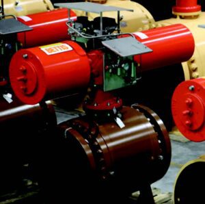
As critical units in a Safety Instrumented System (SIS), Emergency Shutdown valves (ESD) are widely utilised in oil, gas, and chemical processing facilities.
By Guilin Zhou(Garen Zhou), Senior Engineer, Technical Director & Yong Xu(Kevin Xu), Senior Engineer of R&D, Neway
When SIS measuring units detect a potential process failure or dangerous event, ESD valves must rapidly isolate the flow to protect personnel, equipment, and the environment.
ESD valves must function as required during an emergency, yet it has been reported that more than 50% of emergency shutdown device and system failures occur due to these valves. ESD valves include both the valve and the automation equipment; this article focuses on the technical features of the valves and automation.
Technical features & requirements
Valve type – Depending on the application, ball-, butterfly-, and gate valves, with an actuator in combination with control systems, could be used as an ESD valve. Typically, NPS 8 and smaller ball valves or gate valves are selected, while butterfly valves are generally used in larger sizes. Larger size ball valves are generally used in FPSO due to the higher flow and sealing performance.
Sealing performance – According to API 553-2012, ESD valve seat sealing shall perform at ANSI/FCI70-2 Level IV as a minimum. When the pipe medium is hazardous, toxic, or the application requires a higher sealing performance, the seat sealing must comply with Level V or VI per ANSI/FCI70-2, or up to no visible leakage as per API 598.
Fire-safe requirement – ESD valves shall be of a fire-safe design in accordance with API607 or API 6FA.
Reliability & integrity – ESD valves shall have a high reliability rate. SIL2 certification is a minimum requirement for safety integrity for the entire automation package with various functional actuators. In addition, as part of a SIS system, ESD valves are generally independent of distributed control systems in software and hardware. They should not be part of the process control of normal operations. Manual operation devices could potentially reduce reliability and affect the function of ESD valves, which is not recommended.
Automation features & requirements
According to API 553-2012, the automation for ESD valves could include a pneumatic, electrohydraulic, or electric actuator. Selection is based on piping engineering, site conditions, cost, and the user’s objective. Electrohydraulic actuators are generally considered as a first option; they are widely used where very high thrust force is required. However, pneumatic actuators are preferred when a reliable air supply is available. This article mainly outlines the use of pneumatic actuators.
Pneumatic actuator – Spring return type pneumatic actuators with FC effect in control are typically preferred. If a double-acting actuator is selected, the specific air supply or air storage tank shall be taken into consideration. The cylinder size and control attachments shall be calculated and determined to function with the minimum air supply pressure.
Control logic – According to API 553-2012, pneumatic actuators are generally of the fail-to-safety type. When the system fails, they ensure process safety or aim to create a safe state. In the event of instrument air failure or solenoid valve power failure, the ESD valve closes quickly and needs to remain in the closed position.
When the production process needs to return to the normal condition, the SIS can’t directly control the ESD valve to open. The ESD valve can only be opened after checking site equipment and a reboot.
Solenoid valve selection
Normally, SIS systems only permit the use of a direct-action solenoid valve. The pilot solenoid valve has the risk of reducing system integrity. The solenoid valve shall use 24V DC electricity and be directly controlled by SIS system. In explosive and dangerous conditions, the solenoid valve shall be Exd or Exia type. When Exia type is selected, isolation safety grids should be used. The solenoid valve protection grade should not be lower than IP65.
As recommended in API 553-2012, a solenoid valve in SIS is preferred for power reduction (long-term excitation type). Also, the solenoid valve is not allowed to force or reset to the normal position. If the solenoid valve must be excitation action, it is recommended to use a diagnostic loop and arrange regular high-frequency tests to ensure its reliability.
Diverse redundant structures
- out-of X SOV arrangement – While this configuration has high safety, it also increases the risk of spurious trip rates in the system. In the 1OO2 structure shown in Figure 1, the loss of power to any of the solenoid valves will lead to ESDV closure.
- out-of X SOV arrangement – This configuration has high availability and reduces the risk of spurious trip rates in the system. However, it also reduces system safety. In the 2OO2 and 2OO3 structures shown in Figures 2 & 3, loss of power to any of the solenoid valves will not cause ESDV action. The ESDV will only close if two or more solenoid valves lose power simultaneously.


Torque/thrust and safety factors
API 553-2012 requires the pneumatic actuator output torque/thrust to have a safety margin of 25% to 40% relative to the valve-required input torque or thrust. However, a two-times safety factor is recommended for the output torque/thrust for a pneumatic actuator, based on actual industry experience.
Response time
Theoretically, ESDV response time should be as short as possible. However, the valve and piping performance must be taken into consideration. For the piping of liquid media in particular, a short ESDV response time may lead to the water hammer in the pipeline and damage to the equipment. Therefore, the response time shall be defined by considering the working flow parameters. As per API RP 556 2nd edition, which specifies the maximum allowable response time as below for SIS valve:
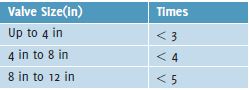
There are obvious differences between different standards for ESDV response times. Normally, based on the valve design and application, it is recommended to define one second per inch of valve size for closing and five seconds per inch for opening unless otherwise specified.
Fire-safe requirement
Pneumatic actuators, including the cylinder and attachments, shall have fire-safe protection. The fire-proofing jacket must comply with the UL 1709 standard, protect the actuator, and sustain its temperature below 93°C during a 1093°C fire burning for 30 minutes.
Partial stroke test function
The ESD valve is part of the SIS and only switches on and off in emergencies. It stays in a static state during normal production processes, which means that it is impossible to check the stability of the valve. Personal intervention to test the valve can easily cause the valve to switch fully and affect the production process, in conflict with the high safety performance level requirements (SIL2 and above). See Figure 4.
The PST function could periodically test the valve for proper operation without affecting process operation. This also improves the SIL rating of the ESD valve. At present, ESD valves can realise the PST function in the following three ways:
- Mechanically – Generally, cam valve +PST manual valve is used to achieve PST function. It is simpler and more economical than other methods. However, this method requires personal operation on site as remote control is not possible; this method is not safe as external factors can easily interfere.
- Limit switch + PST solenoid valve – relatively economical and can realise local and remote control PST tests. However, the PST angle is not adjustable.
- Intelligent positioner/ intelligent solenoid valve/ intelligent limit switch – This PST function is mainly realised by intelligent components, which generally include: DVC6200 SIS digital positioner, IMI MAXSEAL ICO4-PST series solenoid valves, and TOPWORKS D-ESD series limit switches etc.
These above typical intelligent components can not only realise the PST function, but also have an online diagnosis function, which can monitor the valve status throughout the process. This method is becoming increasingly popular to realise the PST function.


References
API RP 553-2012, Second Edition: Refinery Valves and Accessories for Control and Safety Instrumented Systems.
API 6DX-2023, Second Edition: Standard for Actuators and Mounting Kits for Valves.
SHELL DEP 32.36.01.18-2019: Selection and Procurement of Actuators for On-off Valves.
GB/T 50770-2013: Code for design of safety instrumented system in petrochemical engineering.
DEP-T-PE1530-2017: Design Guidelines for Emergency Block Valve(Tentative).
IOGP S-707-2020: Supplementary Specification to ISO 12490 Actuators for On-off Valves.
UL 1709-2022: Rapid Rise Fire Tests of Protection Materials for Structural Steel.
About this Featured Story
This Featured Story is an article from our Valve World Magazine, April 2023 issue. To read other featured stories and many more articles, subscribe to our print magazine. Available in both print and digital formats. DIGITAL MAGAZINE SUBSCRIPTIONS ARE NOW FREE.
“Every week we share a new Featured Story with our Valve World community. Join us and let’s share your Featured Story on Valve World online and in print.”