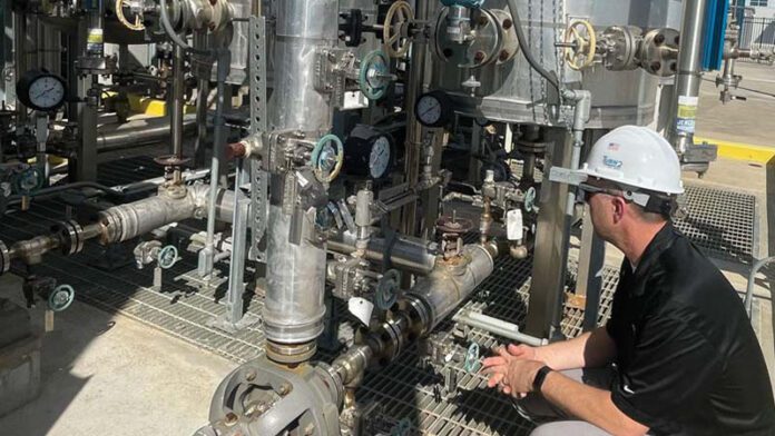
The industrial valve industry has thousands of products for any application intending to move process fluid from one location to another. But, the industry has a problem. Leaking valves result in fugitive emissions, the unintentional release of process fluid into the environment, and can result in increased maintenance costs, fines, and damage to equipment and personnel, costing producers millions of dollars annually.
By Nick Runyon and David Yakos, Co-Founders of MagDrive Technologies, Inc.
Within the oil & gas industry, leaks from valve packing chambers account for roughly 60% of fugitive emissions. Over 90% of valve leaks result from failure in the packing at the valve stem. Valve packing creates a dynamic seal at the stem which is prone to leak over time with use. Each year brings advancements to sealing, packing, and gasket technology with the promise to curb the industry’s fugitive emissions problem. As fugitive emissions regulations tighten, technological breakthroughs in monitoring and imaging improve our ability to locate and measure leaks. Today we can identify and mitigate this severe problem better than ever before. But, rather than treating the symptom, why not eliminate the problem at its source?
Magnetic automation made possible
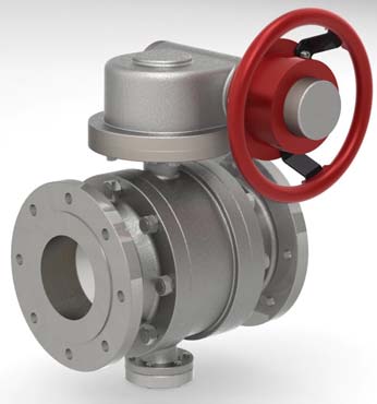
Magnetic actuation of industrial valves is now moving the industry from low-e to zero-e. With valves fitted with a magnetically actuated valve drive, the valve stem is encapsulated with a solid wall chamber. The valve is operated by a pair of magnetic arrays linking the handle or actuator to the valve stem safely sealed inside.
Recent advancements in technology and design have solved some of the biggest problems with magnetic actuation. Now, not only is it possible to generate enough torque to operate any valve of nearly any size, but manufacturers can also calculate the exact torque requirements to eliminate the possibility of breakage in the field.
Advancements in magnetics and new mechanical discoveries have opened up applications for high pressure and a wide range of temperature applications from cryogenic to higher temperatures. Magnetically driven valves have been validated through some of the most stringent API tests and applications, verifying the true potential of zero emissions through magnetic actuation.
Tested and approved
MagDrive Technologies is the leader in the magnetic actuation category. In an API 6FA test, a gate valve was fitted with a MagDrive operator, completely encapsulating the stem and eliminating the leak path of exposed stem packing. This fire test is often catastrophic to valves when measuring how much they leak, as they are aggressively heated and cooled. The valve fitted with the magnetic operator maintained a solid wall, eliminating the flow path to atmosphere, and continued to perform 44,000 actuations after the valve cooled, all without leaking.
When considering safety concerns with lethal services, environmental hazards, or maintenance nightmares with chronic leakers, one immediately begins to realize the benefit of zero-e magnetically actuated valves. Magnetic actuation can eliminate fugitive emissions in the harshest environments in the most challenging locations. Magnetic actuation can be applied to various manufactured valves regardless of the brand, size, or application.
The journey so far
New technology often emerges from attempts to solve the most complex problems. The validation of magnetic actuation as a viable solution to fugitive emissions started when MagDrive Technologies worked with NASA to contain cryogenic helium to true-zero fugitive emissions standards for NASA’s Morpheus planetary landing vehicle. Helium is often used in space vehicles to pressurize fuel tanks. Helium is the smallest element on the periodic table and is notoriously difficult to contain. To minimize size and costly payload, NASA wanted to store the helium at cryogenic temperatures, -269 degrees to -300 degrees Celsius.
Initial attempts to contain helium applied current technology and thinking, resulting in a six-foot stem packing design to isolate the packing from the cold. This valve stem was bulky and still resulted in leaks. By shifting to magnetically driven valves, NASA achieved true-zero emissions with cryogenic helium at 3500psi. Helium was successfully contained in this first-of-its-kind test without a leak path at extreme pressures and temperatures.
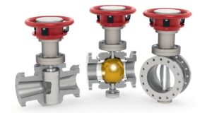
MagDrive valve technology is now applied to contain other materials such as hydrogen (H), methane (CH4), and even lethal chemicals like phosgene (COCL2) or hydrogen sulfide (H2S). This research effort allows Zero-e magnetically driven valves in quarter-turn formats, including ball, butterfly, and plug valves. Rising stem/linear valves, including gate and globe, can also be fitted for magnetic actuation.
Industrial grade torque
Using magnets is a familiar concept in the oil and gas industry. Magnetically driven pumps have eliminated external leaks for decades and set a precedent for magnetics. Magnetic pumps isolate the shaft, like magnetic valves, separating the stem from the actuator with a leak-free chamber. However, magnetically driven pumps operate at low torques and high speeds. Valves typically operate at low speeds and higher torques, and up until now, the challenge has been to derive the required torque necessary for commercial, industrial valve applications.
The torque requirements to operate a valve can be very high to break free or open and close the valve. MagDrive Technologies solved the problem of delivering torque from small valves to large pipelines. For example, MagDrive was tested on a 4” Naval globe valve for high temperature and high torque requirements.
The US Navy wanted to ensure the magnetic interlock could deliver enough torque to the valve stem in any environment and ordered a stress test. The MagDrive team engineered the valve drive to intentionally cause a valve stem failure. During the trial, the valve was blocked while the magnetic coupling continued to stress the valve stem. The magnetically actuated valve drive twisted the ∞” valve stem, proving that more than enough torque could be delivered through magnetics while shattering misconceptions about magnetically actuated valves.
The US Navy stress test demonstrates a key feature and benefit of magnetic actuation. Magnetic interlock can be precisely designed. Rather than shattering valve stems, torque requirements can be calculated and backed down from the valve or valve stem breaking point. Rather than causing a valve failure, engineers can set the magnetic array to jump to the next magnet right before a stem failure occurs. This result is an infinite shear pin protecting the valve from scenarios where an operator might attempt to open or close a valve with an oversized valve wrench and otherwise cause a valve failure.
Reduce LDAR expenses
The immense cost of fugitive emissions is the sum of many different contributors. Serious revenue is lost whenever facilities experience downtime. End users pay extraordinary amounts for compliance fines and to conform to content decrees. Magnetic actuation can eliminate the offending leaks and, along with them, the penalties incurred. Maintenance on a leaking valve costs much more than the valve itself when factoring in procurement, maintenance, and downtime.
Magnetically actuated valves can minimize or eliminate regularly scheduled maintenance for failed packings. Encapsulated valve stems do not allow the packing to leak into the atmosphere and entirely contain the process fluid. Magnetically actuated valves eliminate dynamic seals and the associated monitoring requirements. With magnetic actuation, the valve can now be considered a flange-to-flange connection claiming ‘no detectable emissions.’
Temperature
Magnetically actuated valves can eliminate leaks ranging from the coldest to higher temperature applications with only a few exceptions. Specific magnets can maintain a magnetic field from cold cryogenic temperature (sub 200 °C) up to 350 °C. Other magnets can withstand upwards of 500 °C without compromising magnetic coupling. Most lines don’t reach these extremes, but for some high-temperature applications, the magnetic coupling needs to be thermally isolated from the process line, keeping them within the specified temperature range. Cryogenic valves often require an elongated stem to move from hot to cold, separating the packing from the chilly process fluid. Cold temperatures can compromise and embrittle the packing, causing leaks in traditional valves. As an added benefit, some magnets increase their magnetic field when cold, so magnetic actuation is a dream in cold conditions.
The new category of zero-e
Magnetically actuated valves are the longest-lasting zero-e solution. Often compared to bellows valves, a magnetically operated valve differs significantly from a bellows product. The solid wall encapsulating the valve stem is not prone to crack or wear like a bellows valve because it is not moving and breaking through actuation. Instead, the magnets float on an air cushion, resulting in minimal wear and extended valve life. Magnetically actuated valves have a smaller footprint and height than comparable bellows valves which are taller to accommodate the bellows design.
This new technology is now available as magnetic actuation has moved from successful research and development through testing, validation, and commercialization. Magnetically actuated valves provide a zero-e solution for those looking to eliminate environmental hazards, dangerous emissions, and costly leaks while increasing health, safety, and the bottom line.
