Over time, emissions legislation has become increasingly stringent. The Environmental Protection Agency in the USA and the Industrial Emissions Directive in Europe agree that industrial valves account for the majority of fugitive emissions in oil refineries. They also agree that most of these emissions are caused by frequently operated rising stem valves.
By Hans Dekker, A.W. Chesterton Co.

There are several factors that make sealing these frequently operated valves particularly challenging. Environmental legislation requires low levels of fugitive emissions. Frequent stem actuation causes the packing to lose volume and increases leak rates, making the low emission requirement difficult to achieve. Operators also demand accurate valve response, which requires low stem friction. Refineries typically handle flammable liquids at relatively high temperatures and require the use of fire safe materials. These four requirements combined make this particular valve application particularly challenging.
Packing rings installed in a stuffing box work by converting an axially applied force into a radial direction by the principles explained in Pascal’s law. Approximately half of the axial load is converted to radial load. The resulting radial stress gives rise to two forces: a sealing force and a frictional force. The higher the force applied to the gland follower, the higher the sealing force (and therefore lower the leakage) and the higher the frictional force.
Since our goal is to achieve the lowest possible friction and the lowest possible leakage, we need to find a gland force that produces a sealing force and a friction force that are both acceptable. See the green area in Figure 2.
Friction
In control valves in particular, the friction generated by the packing is extremely important. Plant designers recommend that control valves should respond to signals of 1% or less to effectively reduce process variability. However, it is more common for valves sealed with standard graphite packing to have a dead band of 5% or more, resulting in late stem response, overshoot and therefore high process variability.
The consequences of this friction issue are:
- Failure to achieve full production capacity.
- No optimum control of the final product specification.
Packing stress and leakage
Another important point in relation to control valve stem sealing is that continuous stem movement leads to packing relaxation and extrusion. The dotted line, indicating the current packing stress, moves to the left (Figure 3) due to the loss of packing volume. This results in less friction, but also in increased leakage. Knowing that some valve end users have requested low emissions performance in combination with low stem friction for over 4-5 million stem cycles proves that this is a very realistic scenario.
And it is leakage that is the problem, because fugitive emissions are estimated to account for 50% of total plant emissions, and 50-60%of fugitive emissions come from valves and particularly the stuffing box.
Frequently operated valves, such as control valves, are more likely to leak than static valves. Rising stem valves are more likely to leak than quarter turn valves. The majority of fugitive emissions are caused by a small proportion of equipment. In fact, less than 1%of gas/vapor service valves can account for over 70% of a refinery’s fugitive emissions.
As a result, many valve emission standards have been introduced around the world. Some examples are API 622, API 624, API 641, and ISO15848-1.


High temperature applications
Friction and leakage are not the only requirements we have to deal with. In the oil and gas industry, we have high temperature applications that present us with additional challenges. Seals also need to be fire resistant, which makes the task even more challenging. API 607 and 589 are examples of fire tests. So there is a whole range of requirements, and not all available materials are good at all of them.
The main materials used for valve packing are graphite and PTFE, both of which have their advantages and disadvantages. It is clear that a combination of graphite and PTFE is required to produce a sealing system that meets all the requirements of a control valve seal. Another factor is thermal expansion. There is too much difference between the coefficient of thermal expansion of PTFE and the coefficient of thermal expansion
of the metal components. As a result, we see leaks during thermal cycling that have to be compensated for, for example, by live loading. Graphite performs better in thermal cycling, and it has better friction at higher temperatures. So thermal cycling between, say, 150°C and 315°C gives better performance than, say, ambient to 315°C. Less friction means less wear, which means less packing volume loss, which means less leakage.
Therefore, as the temperature changes rapidly from hot to cold in a fire test, the performance of graphite can be improved by adding a PTFE element. Different seal manufacturers have developed different designs. Many of them consist of PTFE and graphite for the reasons mentioned above. In general, the PTFE content is kept low to minimise the negative effects of PTFE in a fire test.
There are other measures that can help and are commonly used. 


Packing
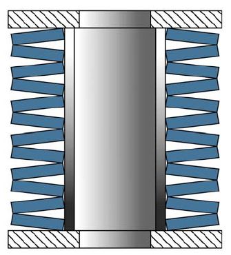
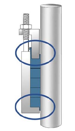
Packing sets in control valves lose volume due to wear and relaxation. Standard stuffing boxes do not have the ability to compensate for this volume loss and the only method is to reapply the torque after some time. This is highly undesirable, of course. One method of making the stuffing box maintenance free is to fit a spring element under the gland nuts to compensate for any volume loss that the packing set may have (live loading). Another factor to consider is packing extrusion (Figure 7).
Graphite and PTFE can be sensitive to extrusion and the solution to this is anti-extrusion rings. These can be made from reinforced graphite, carbon fiber packing or high-density graphite rings. The last point to mention is that packing installation and valve condition are as important as the correct seal selection. Therefore, these factors have to be considered as well.
Conclusion
High-temperature, low-emission, low-friction, fire-safe sealing on control valves is challenging because no single sealing material has the properties to perform all these functions adequately. Graphite and PTFE combinations perform well. Lowest class sealing can be guaranteed for well over 100k cycles at high temperature and fire safe with graphite-PTFE combinations.


About the author
 Hans Dekker graduated as a Bachelor of Engineering at the. Saxion Polytechnic in Enschede in the Netherlands. He has been working in the sealing industry for over 25 years in various functions in Engineering and Marketing. He is the Product Line Manager in Europe, Middle East and Africa for Compression Packing and Gaskets for the A.W. Chesterton Company. Hans is an active member of the European Sealing Association.


