
This article serves as a technical guide for specifying bellows balanced pressure relief valves, detailing when and why to use them instead of conventional valves, particularly for applications involving variable backpressure or challenging fluids.
By Artur Cardozo Mathias
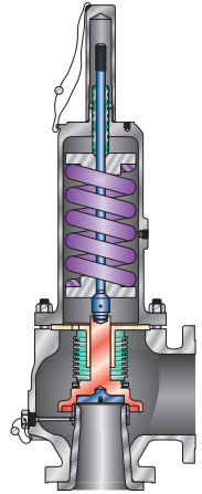
In an industrial process, there are several types of fluids that have characteristics that can result in the jamming of the moving components of a conventional design pressure relief valve, such as the disc support in the guide, including the stem in the upper spring support and in the spring adjustment screw. They can be with or without a manual lever.
Applications subject to backpressure – bellows with balancing function
When a conventional design pressure relief valve discharges into a manifold that is kept constantly pressurized, the pressure existing at the discharge connection (outlet flange) of the valve before it opens is called “constant superimposed backpressure”. In such cases, if the fluid is clean, non-viscous, non-corrosive and has no tendency to crystallize or polymerize, the user can specify a conventional valve.
The valve manufacturer should be informed during purchase of the backpressure value. In this way, the manufacturer makes a differential adjustment (CDTP) in the set pressure, that is, the value of the constant superimposed backpressure is subtracted from the value of the set pressure for the valve to open in the process, and under real operating conditions. In turn, the manufacturer will select a spring whose set pressure desired by the user is within the spring adjustment range.

When the backpressure is of the variable superimposed type, that is, its value can range from zero (if the collector is empty at the time of valve actuation) to a maximum value pre-established during the collector design phase, then the user must specify a balanced pressure relief valve with bellows. The bellows have the function of canceling the effects of the variable superimposed backpressure on the value of the valve set pressure. This cancellation occurs in both the radial and axial directions of the bellows, since the effective area of the bellows is equal to or greater than the sealing area of the disc and nozzle. Consequently, the valve will open at the same value obtained on the test bench (within the tolerance allowed by the ASME Code – Section XIII – in Table 3.6.3.1- 2 – 2023 Edition), under ambient temperature and atmospheric backpressure, considering the compensation for the cold differential adjustment to correct the effects of the fluid temperature on the mechanical characteristics of the spring.
Balanced pressure relief valves with bellows are also recommended for applications in which the build up backpressure is greater than the overpressure value achieved under relief conditions. In a conventional valve, the limit of this type of backpressure is 10% of the valve set pressure for an overpressure also of 10%; consequently, one value cancels the other and the disc lifting stroke is not reduced, just as the valve flow capacity is not reduced.
Bellows with isolation function
However, there are applications in which the fluid may be corrosive, viscous, with a tendency to crystallize or polymerize. If such fluids are lodged in the gap between the guide bore and the disc support shaft in a conventional valve, the fluid may fill that gap, rendering the valve inoperative. To avoid these situations, it is recommended to specify balanced valves with bellows, with the bellows having an isolation function.
Even when the backpressure is of the constant superimposed type, but the fluid is dirty, corrosive, containing solid particles in suspension, with a tendency to crystallize or polymerize or very viscous, it is also recommended to specify a balanced pressure relief valve with bellows. In these applications, even if the backpressure is of the constant superimposed type, there is no need for cold differential adjustment (CDTP) to compensate for the effect of the backpressure on the valve set pressure value, as is mandatory for a conventional valve.
In applications for fluids with the characteristics mentioned above, the presence of the bellows allows components above the bellows, such as the bonnet, stem, spring, spring supports, spring adjustment screw, adjustment screw lock nut and cap, to be constructed of materials that are less resistant to corrosion, thus reducing the final cost of the valve and installation.
For extremely corrosive applications, such as hydrogen sulfide, the NACE MR 0175 standard requires that the bellows be manufactured in Inconel® × 625.
Maximum set pressure limits
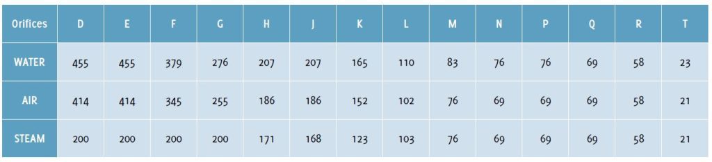
Conventional and balanced valves have maximum set pressure limits that are reduced as the nozzle area and set pressure increase.
The table below shows the set pressure limit values for balanced valves for fluids such as water, compressed air and saturated steam. The values are in barg and were taken from the catalogs of the main manufacturers:
Minimum set pressure
Due to the presence of the bellows, balanced valves have a minimum set pressure that is always higher than that of conventional design valves. This is because the elastic constant of the bellows prevents a lower set pressure. This minimum set pressure is 1 barg (15 psig)
Rupture disc at outlet
If the user wishes to isolate a pressure relief valve from the manifold due to corrosiveness or viscosity of the fluid, he can install a rupture disc on the outlet flange of this valve. However, if this valve is conventional, a leak from the upstream side can increase the pressure between the nozzle outlet and the rupture disc. For these applications, it is also recommended to specify a balanced bellows valve.
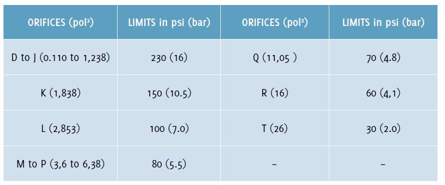
Backpressure limits according to API Std. 526
The table below shows the pressure limits recommended by API Std. 526 at a temperature of 100°F (38°C). Because of the presence of the bellows, the backpressure limits are lower than those allowed for conventional design pressure relief valves. For example, a conventional design valve with a Class 150 outlet flange is 285 psig at a temperature of 100°F (38°C). For temperatures above 100°F, the pressure limits are lower. The valve manufacturer should be consulted for higher temperature and back pressure values.
Facilitating reseating in applications with low set pressures
The bellows can also be applied to larger valves, for example, for Q, R and T orifices, at set pressures below 3.0 barg (43.5 psig) even if there is no variable backpressure and the fluid is clean.
This recommendation is to facilitate the reseating of the disc during the pressure relief phase of the valve. The presence of the bellows facilitates this reseating, that is, the reseating becomes smoother when compared to a conventional valve for the same conditions of size, type of fluid and adjustment pressure.
Relief hole in the bonnet
Every balanced valve with bellows must have an open relief hole in the bonnet. This hole has two functions: the main one is to keep the pressure inside the bonnet equalized with the atmospheric pressure (acting in an area equivalent to or greater than the sealing area of the nozzle, consequently, there is no pressure to push the sealing disc downwards and against the inlet pressure). This open relief hole also prevents the bellows from breaking during valve operation. This rupture could occur due to the reduction in air volume inside the bonnet if there were no relief hole, and consequent increase in pressure caused by the disc elevation stroke. A secondary function for this hole, also known as a “sentinel hole”, is to monitor the physical integrity of the bellows. A punctured or cracked bellows should always be immediately replaced or removed from the valve, especially if it is operating with fluids that tend to crystallize, since the accumulation of this fluid inside the bellows can limit or prevent the disc from lifting during valve operation.
For corrosive environments, this relief hole must be routed to a safe location to prevent the disc holder from jamming with the valve guide and also the stem from jamming with the spring adjustment screw. For toxic or flammable fluids, this hole must also be routed to a safe location.
Reduction in the flow capacity of the bellows balanced valve
The presence of the bellows, due to the space occupied inside the valve, reduces its flow capacity whenever it is operating under backpressure conditions, in addition to increasing the fluid flow speed. To correct this reduction in flow capacity, correction factors (Kw and Kb) are used whenever the fluid is a liquid or gas, respectively. The valve manufacturer should be consulted for the value of the correction factor to be applied in the calculations for sizing the nozzle area. Due to the reduction in flow capacity and the use of the correction factor, the calculated minimum required nozzle area results in a larger area than if there were no backpressure or bellows.
Backpressure test on bellows-balanced valves
Any valve that discharges into a manifold, whether conventional or balanced, must be subjected to a backpressure test in which the test pressure must be at least 30 psig (2.1 barg). Specifically for balanced valves, care must be taken to prevent bellows collapse due to pressure during the test. This test is a requirement of the ASME Code Section XIII, in paragraph 3.6.2 – 2023 Edition. It is required for conventional or balanced design valves with inlet size greater than 1” and which and discharge into a manifold. When the valve is of the conventional type and discharges to the atmosphere, and the bonnet is of the closed type, the backpressure test can be dispensed with.
Conclusion
Balanced valves with bellows should be specified and applied whenever there is a variable backpressure in the manifold or a build up backpressure in the discharge piping at a value greater than the maximum overpressure achieved under relief conditions for a conventional design valve or when the fluid is dirty, viscous, corrosive, and may crystallize or contain solid particles in suspension.
About this Technical Story
This Technical Story is an article from our Valve World Magazine, December 2024 issue. To read other featured stories and many more articles, subscribe to our print magazine. Available in both print and digital formats. DIGITAL MAGAZINE SUBSCRIPTIONS ARE NOW FREE.
“Every week we share a new Technical Story with our Valve World community. Join us and let’s share your Featured Story on Valve World online and in print.”