
Valves are widely used in industrial fluid control systems to start, stop and direct flow. For the efficient and safe operation of these systems, it is of great importance to calculate the torque required when opening or closing the valves correctly. In this study, the concept of torque, the mechanisms of torque formation in valves, torque calculation methods and application examples are examined in detail.
Text and images by Kemal Comakli PhD, Mechanical Engineering, Omer Yildiz, Mechanical Engineering, Starvalve Process Valves and Actuator Technology Industry and Trade inc.

Introduction
In industrial fluid control systems, valves provide operational efficiency and safety by regulating fluid flow and pressure. The rotational force required to open or close valves, i.e. valve torque, is a critical parameter that directly affects actuator selection and the overall energy efficiency of the system (ISA, 2020).
Valve torque is calculated to allow for proper actuator sizing and to provide assurance that valve components can withstand the internal forces created by the flowing fluid and pressure. Pressure loss characteristics must be known to estimate torque, and system designers also use this data to calculate pump pressure requirements and evaluate energy costs associated with pressure loss across the valve in pumping applications. Cavitation is analysed to prevent unwanted noise and vibration and to prevent damage to the valve and adjacent piping.
Valve manufacturers publish torque values for their products so that the actuator and mounting hardware can be properly selected. However, published torque values usually represent only the seating or opening torque of a valve at its nominal pressure. While these are important values for reference, published valve torques do not take into account actual installation and operating characteristics. In order to determine the actual operating torque for valves, it is necessary to understand the parameters of the piping systems in which they are installed. Factors such as installation orientation, flow direction and fluid velocity of the medium all affect the actual operating torque of valves.
Torque definition and equation
Torque is the effect of a force applied to an object to rotate that object around an axis. It is also called “moment” in engineering and is an important quantity, especially in rotating systems.
Torque refers to the turning effect of force and is defined as follows:
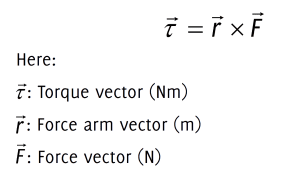 In this formula, torque is found by multiplying the perpendicular components between the force and the distance from the point of application of the force to the centre of rotation.
The angle between the force and the position vector is θ:
τ = r · F · sin(θ)
Here:
τ: Torque (Nm)
R: Distance between the rotation axis and the force application point (m)
F: Magnitude of force (N)
θ: Angle between force vector and position vector (degrees or rad)
Important note:
- Torque is a vector quantity. That is, it has both magnitude and direction. The direction is found using the right-hand rule.
- The greatest torque is obtained when the force is applied perpendicular to the position vector (θ=90°, sin (90°) =1). If the force passes through the axis of rotation or is parallel to the position vector (θ=0° or θ=180°, sin(0°)=sin(180°) = 0), the torque is zero and there is no turning effect.
Torque calculation in valves
Torque calculation in valves means determining the rotational force required to open or close the valve. This calculation is vital for the correct selection of actuators, especially those used to automatically control valves. Choosing an actuator with the wrong torque value can lead to improper valve operation, premature failure or problems in the system.
Factors affecting torque in valves
There are many factors that affect the torque required to open or close a valve:
- Valve size (diameter): Generally, larger diameter valves require more torque because they have a larger surface area in contact with the fluid.
- Fluid pressure: As the fluid pressure inside the valve increases, the force exerted on the valve flap or ball also increases, creating a greater torque requirement to move the valve.
- Viscosity of the fluid: More viscous (denser) fluids (such as oils) can create more resistance on the moving parts of the valve, increasing the torque requirement.
- Valve type: Since the operating principles and internal structures of different valve types (ball valves, butterfly valves, gate valves, globe valves, etc.) are different, their torque requirements also vary. For example, quarter-turn valves such as butterfly valves or globe valves exhibit different torque characteristics than linear motion valves such as gate valves.
- Seal material (seal type): The material and design of the seals affect the coefficients of friction. High friction seals may require more torque to move the valve. For example, a valve with a rubber seal may require less torque than a valve with a metal seal.
- Friction: Friction between moving parts within the valve (bearings, seals, etc.) directly affects torque. Dirt, corrosion, or inadequate lubrication can increase friction.
- Temperature: High temperatures can change the properties of some materials, which can affect the torque requirement.
- Operating conditions: Environmental factors such as how often the valve opens and closes, vibration and impact can also play an indirect role in torque calculations.
Components and situational variability of valve torque
Valve torque is not a fixed value; it is generally divided into three basic components (Crane, 2018):
| Torque Component | Explanation | Affecting Factors |
| Starting Torque | The torque required to initially move the valve. | Seal compression, friction forces |
| Working (Flow) Torque | The torque developed as the valve moves during flow. | Flow pressure, velocity and fluid forces |
| Seating Torque | The torque required to keep the valve fully closed or fully open. | Fluid pressure, sealing force |
While only mechanical frictions are measured prior to assembly (idle/dry testing), once assembly and flow come into play, torque requirements increase due to flow forces and hydrodynamic effects (ISA, 2020).
Torque calculation in valves
Torque calculations for valves are often done using complex engineering formulas and experimental data. Specific torque values for each valve type and size are provided by valve manufacturers. These values are obtained by testing the valve under specific operating conditions.
In general, the opening and closing torque of a valve consists of two main components, namely static torque and dynamic torque:
- Static torque (starting torque): The friction force that the valve must overcome after being closed for a long time or at the first moment of movement. In particular, conditions such as seals sticking to the valve or solidification of the fluid can increase the static torque. This is usually the highest torque value required to move the valve.
- Dynamic torque (operating torque): The torque required when the valve is in motion (opening or closing). This is usually lower than the static torque because friction decreases once motion has begun.
When selecting an actuator, the static torque value, which is the highest torque requirement of the valve, is taken as a basis. Usually, a safety factor is added to the valve torque value to select the actuator, which can usually be 25% or more of the valve torque value. This allows for an allowance for possible unexpected friction increases, fluid viscosity changes or corrosion.
Valve manufacturers usually specify “opening-closing torque” values (in Nm) for certain diameters and pressures in their catalogues or technical data sheets. These values are used directly when selecting an actuator.
General approach for torque calculation in valves
Valve manufacturers determine the exact torque values by performing detailed tests for their specific valve designs and materials used. These values are usually presented as a series of curves or tables and are used for actuator selection.
However, to roughly express the main factors that affect the torque required by a valve, we can consider the following equation:
τvalve = (Fpressure × Rvalve) + τfri + τseal
Let’s explain this equation with its components:
τvalve: Total torque (Nm) required to open or close the valve.
Fpressure: The force (N) exerted by the fluid on the valve flap or ball. This force is directly related to the pressure inside the valve and the surface area of the valve flap or ball. It can generally be expressed as:
Fpressure = P × Aeffective
P: Fluid pressure in the valve (Pa or N/m2).
Aeffective: Effective surface area (m2) on which the pressure acts. This area varies according to the valve type (e.g. the area of the disc of a butterfly valve, the area of the sphere of a ball valve).
Rvalve: Represents the effective radius (m) or moment arm from the point where the pressure force is applied to the axis of rotation. This varies according to the design of the valve.
τfriction: The torque component (Nm) resulting from mechanical friction between the valve’s bearings, gears or other moving parts. This value depends on the valve size, shaft diameter, bearing materials and lubrication. It is usually determined experimentally.
τseal: The torque component (Nm) resulting from the friction force exerted by the sealing elements (seals) on the moving parts of the valve. The seal material
(PTFE, NBR, metal, etc.), the design and tightness of the seal greatly affect this value. This is usually determined by experimental data.
While the equation above shows the main components that affect torque, there is no single universal equation that can provide accurate calculations for every valve type and size, for the following reasons:
- Complex geometries: The internal geometries of valves (especially globe valves, butterfly valves) are very diverse and it is complex to accurately determine the effective surface area and moment arm on which pressure acts.
- Coefficients of friction: Mechanical friction and seal friction depend on a large number of variables (material properties, surface roughness, temperature, pressure, lubrication status) and cannot be easily expressed with standard formulas.
- Dynamic effects: Dynamic effects such as fluid velocity and turbulence can also play a role in torque, especially at high flow rates.
- Manufacturer data: Valve manufacturers design their valves according to specific standards and perform extensive testing in their own laboratories to obtain the most accurate torque values. This data is the most reliable source for the end user to select the right actuator.
Torque relation according to valve diameter in butterfly valves
In butterfly valves, the torque requirement due to flow forces increases proportionally to the cube of the valve diameter. This means that the dynamic pressure and flow forces acting on the valve disc increase with the cube of the diameter.
Tbutterfly = C · D3 · ΔP
Tbutterfly: Torque (Nm)
C: Experimental coefficient (between 0.01 and 0.03)
D: Valve diameter (m)
ΔP: Pressure difference (Pa)
(Val-Matic , 2019)
Torque relation according to valve diameter in ball valves
Ball valves determine the torque requirement by the effect of seal friction and flow forces. Torque is generally proportional to the square of the valve diameter (Chen et al., 2016):
τball = C · D2 · ΔP
τball: Torque (Nm)
C: Experimental coefficient (between 0.05 and 0.2)
D: Valve diameter (m)
ΔP: Pressure difference (Pa)
This formula provides a practical approach for initial engineering estimates and actuator pre-sizing (Emerson, 2020).
General trends by valve diameter for other valves
Globe valves: Torque requirement depends on sealing forces and shaft friction rather than flow forces. It is approximately proportional to the square of the diameter.
Gate valves: Since they are mostly linear in motion, they are generally expressed as force (F); in rotary actuators, torque conversion is related to the square of the diameter.
Plug valves: Similar to ball valves, torque increases approximately with the square of the valve diameter.
Pinch valves: Torque requirement is generally independent of flow forces; it depends on the friction between the seal and the elastomer.
Summary of components in the torque equation
Additionally, general torque relationships according to valve type are summarised in the table below:
Table 1. General torque relations according to valve types (ISA, 2020; Emerson, 2020; Chen et al., 2016)
| Valve Type | Torque Relation | Torque Increase Trend |
| Butterfly Valve | T≈C ⋅ D3 ⋅ ΔP | Proportional to the cube of the diameter |
| Ball Valve | T≈C ⋅ D2 ⋅ ΔP | Proportional to the square of the diameter |
| Globe Valve | T≈C ⋅ D2 ⋅ ΔP | Proportional to the square of the diameter |
| Gate Valve | T≈C ⋅ D2 ⋅ ΔP | Proportional to the square of the diameter |
Evaluation in terms of energy efficiency
High torque requirements require a larger motor and drive mechanism for the actuator, increasing operating costs and energy consumption (ISA, 2020). To increase energy efficiency:
- Friction reducing coatings and seals should be used.
- Valves should be kept in low friction condition by regular maintenance and cleaning.
- The actuator should be selected according to the maximum torque requirement in the flow.
Conclusion
Valve torque is not a fixed value and varies depending on installation and flow conditions. In butterfly valves, the torque requirement is a cubic function of the valve diameter, while in globe and other valve types it is generally proportional to the square of the diameter. These relationships need to be considered in terms of actuator selection and system energy efficiency.
References available on request.
About this Technical Story
This Technical Story is an article from our Valve World Magazine, August 2025 issue. To read other featured stories and many more articles, subscribe to our print magazine. Available in both print and digital formats. DIGITAL MAGAZINE SUBSCRIPTIONS ARE NOW FREE.
“Every week we share a new Technical Story with our Valve World community. Join us and let’s share your Featured Story on Valve World online and in print.”