This article follows [Part 1 and Part 2] of a series by Mr Neeraj Batra from Chiyoda Corporation.
Definition: The 2015 edition of API 6D Annex K categorizes the common Isolation valves into three categories, namely block and bleed (BB), double block and bleed (DBB) and double isolation and bleed (DIB). However, API 6D clearly suggests that this Annex is informative and the detailed design of the valve shall be considered. ASME B16.34 has no definition about BB/DBB/DIB.
Without discussing the API 6D categorization, we can simply say that BB/DBB/DIB are synonymous terms. These are simply isolation mechanisms and the way to achieve these mechanisms is dependent on the plant’s isolation philosophy. For example, where, what type and how many of them? For a plant operator whose ultimate goal is to close the valve to start a maintenance activity downstream of the isolation valve quickly and safely, explaining valve categorization such as DBB and DIB is meaningless. API’s DBB (pressure acting from both sides and bleed used) category has little practical application in the real world (see Figure 5).
Purpose: As discussed in the isolation philosophy topic, the two main questions answered by the isolation philosophy is the valve type and quantity. The valve type is mainly selected based on the service suitability, leakage class requirement and other secondary factors such as cost, dimensions, pressure drop and operability. Now, the difficult question is: how many?
This question can be answered once a person understands the criticality of the isolation activity and the basic features of the valve. Mostly this point is clearly specified in the client’s isolation philosophy. However, sometimes the client’s isolation philosophy specifies a mechanism like BB/DBB/DIB instead of the type and quantity of valves.
What the process and valve specification engineer can do:
First the process and valve specification engineer has to understand the criticality of the need for isolation and get a consensus from various isolation philosophy stakeholders such as the mechanical or rotating department whose equipment requires isolation, the end user’s experiences, the end user’s isolation philosophy and also the valve vendor’s experiences, etc (see Figure 6). Then the isolation philosophy and P&ID should clearly specify the type and number of main isolation valves, plus the type and number of bleed valves. Of course it can require years of experience to understand the most important valve features.
For example:
• The torque seated butterfly valve is very reliable but has only one seat available for isolation. So, in critical applications two butterfly valves should be selected.
• The torque seated expanding gate valve has two seats available for isolation. So, most of the time just a single valve is suitable even for critical applications. (See Figure 7.) However, it is bulky and costly.
• Although ball valves have two seats available for isolation these valves are position seated and rely a lot on spring force (primary) and upstream pressure (secondary) for isolation. So, two valves are required in case of critical applications.
• Although gate valves are very reliable valves they can’t provide tight shut off. Also, larger size gate valves can be very heavy.
• Globe valves are mainly used for throttling and not isolation. The pressure drop and noise issues are prominent if the valve is used for isolation. However, for rare isolation activities like in bypass lines, globe valves can be considered for isolation.
• For a two seated valve like the trunnion mounted ball valve or the expanding gate valve, a bleed valve can be integrated between the two seats. This bleed can serve two functions, namely to drain the valve cavity prior to any maintenance activity and also to verify that the upstream seat is intact or not. However, the operability of bleed valve shall be studied if the valve will be insulated.
• An assembly of two valves (gate, ball, butterfly, plug) with a bleed between the two is always more reliable than a single valve with two seats and an integrated bleed. However, an assembly of two valves is costly & bulky. The user can consider assembly of two closure members in a single valve to save cost. (See Figure 8)
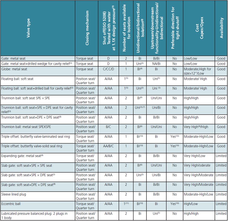
Appendix 1 is an attempt to summarize the features of valves from the isolation perspective. Terms like BB, DBB and DIB should be avoided as there have been conflicting opinions about these terms.
Summary
It is neither the author’s intention nor capability to challenge API 6D requirements. However, the categorization of valves using terms such as BB, DBB and DIB based on API6D for the preparation of an isolation philosophy is not correct as a lot of factors are involved.
1. The leakage class offered will vary from vendor to vendor and hence a clarification with the vendor is required about the leakage class.
2. This clause is for unidirectional and bidirectional capability of the complete valve and not for the individual seats. Focus should be on the complete valve and not on individual seats.
3. A cavity relief feature is required for valves carrying fluids like ethylene, LNG etc. which can expand if heated (mainly by solar radiation) and can pressurize the valve cavity. The direction of cavity relief shall be indicated on the P&ID and physically on the valve.
4. Although a flow arrow is stamped on the valve body which renders the valve unidirectional, the purpose of the arrow is to show the most favorable valve installation for throttling characteristics. A globe valve can provide similar isolation feature if the flow is from above the disc.
5. Although a floating valve/pressure balanced single plug has two available seats, the ball or plug is pushed by upstream pressure onto the downstream seat or vice versa to achieve Isolation.
6. Assuming cavity doesn’t pressurize. The SPE seat itself is unidirectional since the seat can relieve to the upstream side if the cavity pressure reaches a certain threshold value (Normally 6-7 Bar).
7. If the cavity becomes pressurized during the maintenance activity then the SPE seat can relieve. An isolation activity shall not be carried out upstream of SPE seat since cavity can be pressurized.
8. External cavity relief (PSV or bypass line) is required if the fluid trapped in the cavity has the possibility to expand.
9. Very high cost is specified considering the fact that the valve seating area is tungsten carbide coated or chrome carbide coated to prevent seating area abrasion by metallic seats.
10. The direction of cavity relief/favorable flow direction shall be indicated on P&ID and physically on the valve. A flow arrow is not recommended. (See Figure 9.)
11. An eccentric ball valve with two seats is available as an alternative option. (See Figure 10.)


