Severe service valves can be found in non-return, isolation and control functions, although it is recognized that Severe Service Control Valves (SSCVs) do have reasonable industry agreement on what can define severe service. Severe Service Isolation Valves (SSIVs) do not have nearly as clear agreement or understanding.
Identification of severe service conditions for control valves may be determined by performing sizing calculations using IEC 60534-2-1 or ISA 75.01.01 with the following information:
- Fluid state (liquid, gas, vapour, 2-Phase, multi-phase, slurry)
- Flow rate at max, normal and min conditions (Q)
- Upstream pressure at max, normal and min conditions (P1)
- Differential pressure at max, normal and min conditions ((P1-P2) or (dP))
- Vapour pressure of liquids (Pv)
- Temperature (T1)
- Valve size
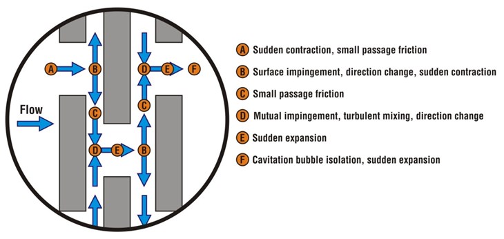
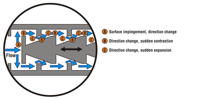
However, it is clear that the further beyond the threshold one gets, the more severe the service. Excellent tools exist to reduce risk and time to perform the multiple calculations that are required to test for the condition thresholds; one of the best is Flowserve’s Performance!, which uses a Valve Selection Guide to significantly reduce sizing and selection inaccuracies and provides clear and abundant data to assist in defining the conditions within and around the control valve.
- Autoclave let-down
- Boiler Feedwater
- Choke valves
- Coal gasification
- Compressor anti-surge
- Engine test stands
- Fluids with high
out-gassing potential
- HP separator drains
- Minimum flow recycle
- Solar power molten salt
- Slurry control
- Toxic/Lethal Service
- Turbine by-pass
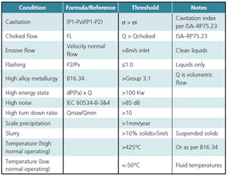
Table 1: Determining factors.
Isolation valves
An important element in selecting SSIVs is the consideration of what can occur while the SSIV is transitioning from its static normal state to the other(Open to Closed, Closed to Open); when it is in dynamic conditions. During this dynamic state, conditions can be vastly different than when static. For example, closing a valve against a normal flow rate from its fully opened position will accelerate the fluid up and until it is stopped by the closed valve, while at the same time decrease its pressure (Bernoulli’s Principle) to a point where it may flash or choke. It is important to have a firm idea of the number of cycles from one starting position to another and the normal position for each application.
There are several typical scenarios: low frequency normally closed (NC), low frequency normally open (NO), frequent NC and NO and equal NC/NO. The frequency of cycling isn’t in itself the challenge, its knowing what happens on each cycle to affect the valve’s health and ability to retain the minimal performance required by the application. If a valve has an allowable leakage rate (see FCI 70.2-2013) like most metal seated valves have, then the fluid can become erosive if the energy level (differential pressure) is high enough to propel the fluid past the closure element, and severe degradation of the sealing elements can occur. This might seem to indicate that a higher number of closed cycles are likely to produce valve health issues than less cycles, but each application has its unique needs, and a valve that only cycles once per year may be as difficult to perform as one cycling once every six hours.
Isolation valve datasheets also often fail to provide a goal or target for installed performance during the valve’s useful life other than the risky assumption that the required valve closure test from API 598, ISO 5208 or MSS-SP-61 can translate a similar quality into the valve’s actual duty and performance in service. Therefore more attention should be focused upon arriving at a reasonable Severe Service Isolation Valve (SSIV) definition, as it is in our opinion, the more difficult task. A severe service isolation valve data sheet lists the key elements that should be identified in order to properly select the type, materials and options of the SSIV, including the information required to determine the effects of the dynamic status like cycle rate and media affects.
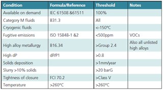
Table 2: Determining factors.
- Isolate over a minimum installed period of time to a minimum quality of isolation (leak-tightness) required by the process
- Be available when required to deliver the minimum isolation performance regardless of dynamic changes in the application
- Operate in hostile environments, in upsets, and with changes in the effects of the media
- Protect the environment and worker safety
- Perform significantly better and longer than non-SSIVs
- Be used where the lack of adequate isolation has a substantial negative affect to facility profitability
- Be used where a single isolation valve requires a second valve in series to isolate
In addition to Table 2, severe service conditions always apply to the following isolation applications:
- Autoclave Block
- Boiler ERV, Drains, Vents
- Catalyst
- Delayed Coking
- Emergency Shut-Off Valves (ESDs)
- Ethylene Furnace Isolation
- FCCU
- Fire Isolation Valves
- H-Oil
- High Cycle Switching/PSA
- High Pressure Slurry Block
- HIPPS
- Hydrocracking
- Hydrogen
- Molecular Sieve/Dehydration
- Reactor Isolation
- SIL Rated Service
- TEOR Steam
- Toxic/Lethal Service
Diagrams courtesy of Flowserve, photographs courtesy of ValvTechnologies and CGIS
