

This article looks at the advantages that new designs for ball valves can bring to flow control, specifically focusing on v-port ball valves.
By Tim Jones, Aalberts Integrated Piping Systems
Precise and reliable flow is essential for any process that requires mixing, metering, dosing, as well as any that needs to adapt to changing process requirements and types of flow conditions. In addition, precise flow control can minimise fluid waste, energy consumption, and reduce process waste, which can help customers adapt to the sweeping trend toward efficiency and waste reduction contained in local and global initiatives and mandates. A new ball valve design provides that reliability at lower cost compared to the more traditional control valves. Ideal for water treatment, food and beverage, power generation, oil and gas, agriculture, chemical processing, pharmaceutical, and biotechnology applications, the new design is less costly to service and maintain over its service life.
Flow rate basics

Generally, flow rate increases with an increase in differential pressure. However, operating a control valve is not as straightforward as this statement may initially seem. As a control valve is cycled, the system curve is altered by changing flow losses. Understanding the dynamic between pressure drops and flow rates during control valve operation is critical for proper system design and valve selection.
Aalberts IPS developed the Apollo® v-port ball valve, which is designed to handle higher fluid velocities and increased pressure drops when the valve is in partially open positions. Throttling a v-port valve results in large pressure drops, but with higher pressure recovery than other control valves. Once the velocity reduces as the fluid exits the valve, a large percentage of the pressure is regained.
Selecting a v-port ball valve for control operations may allow the user to select a more cost effective and smaller diameter valve when compared to using more traditional control valves.
V-port design compared to that of a standard ball valve
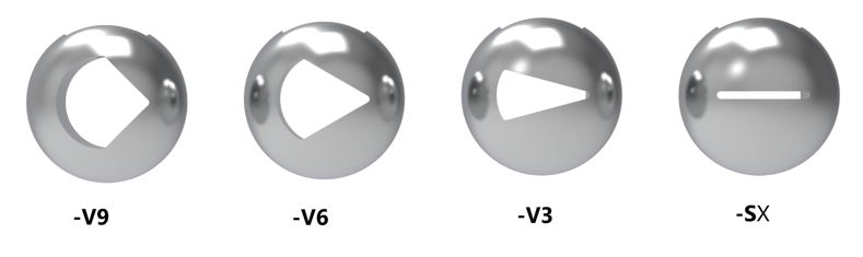
The v-port profile geometries were developed with computational fluid dynamics (CFD) studies and validated with testing to develop the features that control the valve flow coefficient (Cv) curves of each valve size and profile. The profiles achieve a desirable range of flow control and inherent rangeability. The valves share the same platform as the original Apollo® full port and standard port valves, and are offered in 30, 60, and 90-degree Vs for equal percentage flow control and slotted versions for narrow-band linear flow control.
Actuation options reduce need for operator input and offer remote control
The new valve is designed to be mated to a pneumatic or electric actuator, although it is available with a handle for manual operation. Live-loaded packing is a standard option that accommodates the increased cycling experienced by actuated packages. This negates the need for increased adjustments during the life of the packing. Actuated Apollo® v-port valves can be controlled with an input signal to cycle the valve to predetermined set points, or they can be paired with controllers and sensors that provide feedback and automatically adjust the valve position to accommodate changing system needs.
End users will find this to be an advantage because it can reduce the need for operator input to ensure the system is running at maximum efficiency and precision. Systems can also be controlled remotely, providing added layers of safety for hazardous environments, or to mitigate losses during system failures or upsets.
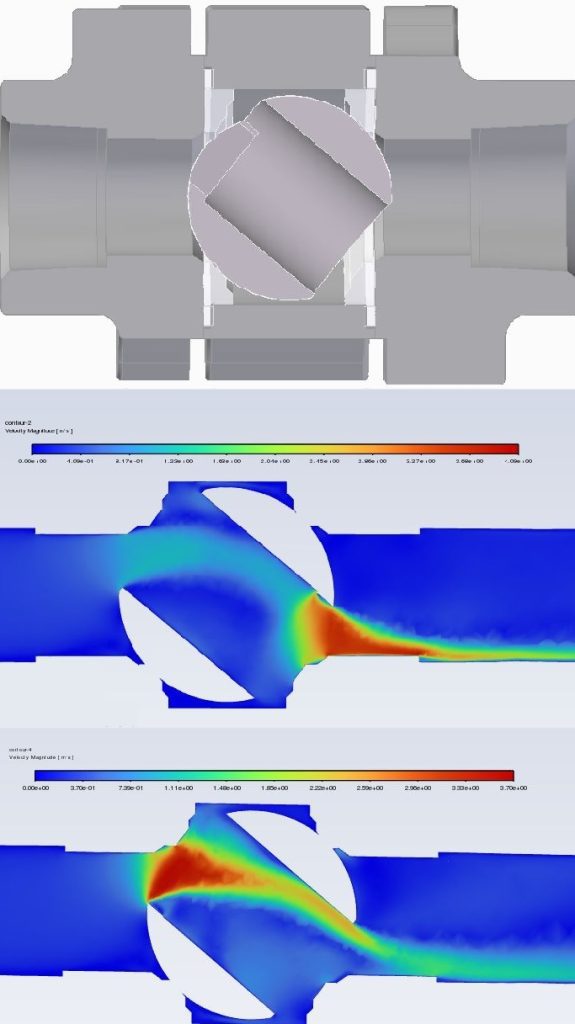
Middle: Velocity on downstream seat with “V” located in downstream position
Bottom: Velocity on downstream seat with “V” located in upstream position
Product development and value proposition
Early in the v-port product development process, the engineering team developed a proposal to replace a customer’s standard ball valves with v-port valves for a wastewater treatment application. An outside firm was hired to study the flow to the wastewater treatment system, and the report concluded that the system supplied significantly more water to the system than was needed. Replacing the existing standard ball valves with the v-port valves, actuation and a programmable logic controller (PLC) with various water quality sensors led to an estimated 55 percent reduction in water usage, amounting to approximately 30,000 gallons of water per day.
Designed for performance, longevity and manufacturability
The ball design includes an upstream characterised profile with a full-diameter bore located downstream. The “V” is positioned upstream to reduce the velocity on the downstream seat. The CFD positioning studies conducted showed that the fluid velocity across the downstream seat’s sealing faces is greatly reduced as compared to positioning the “V” in the downstream orientation. This increases the downstream seat life and extends the bubble tight shutoff performance.
The full bore downstream of the characterised profile allows a quicker reduction in fluid velocity than if the profiles were machined through the full diameter of the ball. In addition to reduction in erosion due to the flow, the flow of fluid that is disrupted as it passes through the characterised profile resolves in less pipe diameters from the outlet of the valve. This is especially useful in systems where space is limited, and fittings must be located closer to the valve outlet than recommended by standard piping practices.
Selecting the right “Apollo” v-port valve for a particular application
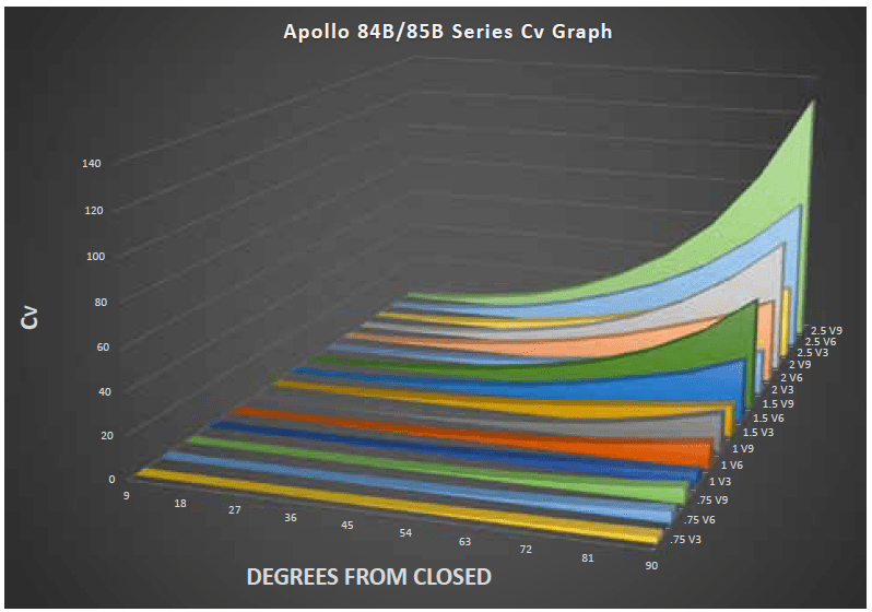
Published Cv charts can be used to select a valve for particular applications, but it is also important to take into consideration what is physically happening to the fluid as it flows through the valve. Throttling v-port valves can result in high fluid velocities, resulting in significant pressure drops. If the Cv charts alone are used, it may lead to selections that have adverse effects such as increased noise, increased valve wear, insufficient flow rate or cavitation. Instead, before selecting the valve for a specific application, users should consult the manufacturer to get assistance in evaluating valve performance and reliability for the application’s fluid and operating parameters.
About the author
 Tim Jones is a Senior Engineer for Aalberts IPS. He has 15 years of experience in fluid systems and component engineering and design. With a sound engineering background in specification driven design and multiphysics simulation, he provides in-depth analyses and novel design for the New Product division.
Dive Deeper into Valve World
Enjoyed this featured article from our April 2025 magazine? There’s much more to discover! Subscribe to Valve World Magazine and gain access to:
- Advanced industry insights
- Expert analysis and case studies
- Exclusive interviews with valve innovators
Available in print and digital formats.
Breaking news: Digital subscriptions now FREE!
Join our thriving community of valve professionals. Have a story to share? Your expertise could be featured next – online and in print.
“Every week we share a new Featured Story with our Valve World community. Join us and let’s share your Featured Story on Valve World online and in print.”