The BFJ’s role is to create a leak-tight sealing load on the gasket material. In the evaluation of the targeted energy, it’s essential to make a distinction between bolt load and clamping load. They are very different. The clamping load is defined as the compressive load on the gasket material at any time in the course of its service.
The bolt load is the load in the bolt at any time in its service life. It must be sufficient to overcome resistances such as hydraulic load and friction, changes in both bolt and gasket characteristics, and uncertainties during the tightening process.
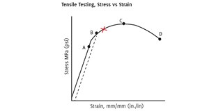
Bolting strength is a first consideration. Figure 1 on the next page identifies the most crucial strength properties of a bolt, from initial tightening to full fracture. The plot is created during ambient temperature and shows the relationship between stress (force/area) and strain (change in length/initial length) as the bolt load is increased. The relationship is linear, initially. Full elasticity is maintained over this range. As the load is removed, the bolt returns to its original length.
Location A (see figure 1, next page) is defined as the proof load. This is a percentage of yield strength, between 85 per cent and 95 per cent.
Ninety per cent is a common value, which we used in our example. A loading at or below the proof strength assures the material remains below its yield value, and entirely within its elastic region. Again, upon removal of the load, the bolt returns to its original length.
Location B is defined as the yield strength. Its value is most often defined by a 0,2 per cent of strain. This property is identified by a line that parallels the initial loading line, but with a 0,2 per cent strain offset and the intersection of the stress-strain plot (shown as the dashed line in Figure 1). To note: the yield strength is not the initial point of yielding. It represents a point at which some yielding has already occurred. Work hardening of the material has taken place. That is, some small volume within the material has exceeded its yield strength. There is a loss of elasticity. The bolt will not fully return to its initial length when unloaded.
Location C represents the highest value of load the bolt can sustain. This is known as the bolt’s tensile strength, also known as ultimate strength. Beyond this value, the cross-section of the bolt begins to diminish (necks down), and progressively lower bolt loads are sustainable. Location D indicates the instant when the reduced area can no longer support any load and the bolt fractures into two pieces.
It’s important to appreciate that this plot is based on ductile bolting materials. Brittle materials result in a very different relationship. For brittle materials, point X becomes the point of fracture. There is less elasticity (not shown), and the fracture point occurs much sooner after the yield strength is reached.
Temperature effects
Elevated temperatures reduce these properties–somtimes, by a significant amount–and should always be taken into account when evaluating the intended clamping load. At elevated temperatures, the bolt will lose some of the stretch that created its initial load. Table 1 below shows how both yield strength and Young’s modulus of elasticity are negatively impacted at elevated temperature for a common piping and pressure vessel bolting material; 25CrMo4.


