The use of numerical simulation during the casting of valve parts provides essential information that cannot otherwise be seen.
By Samuel Venel Simulation Engineer at Inoxyda
Numerical casting simulation technology provides information about physical and thermal phenomena that we cannot see in the actual casting process.
The technology provides information on the filling and solidification phases and the heat exchanges that occur during the cooling. Inoxyda has been casting large-size aluminium bronze alloy pump and valve components using simulation for over twenty years to guarantee quality.
Main interest
The foundry simulation helps us to understand the material behaviour during every phase of the casting process, from the start of the pouring un-til the solidification and final cooling of the part. Its’ use is a major asset in particular to:
• Improve quality
• Optimise production process
• Reduce manufacturing costs
• Predict significant defects
• Conduct experimental plans
Using simulation, we are able to visualise the proper filling of the part and avoid risks such
as soundness, blister, pitting, air traps or sand defects. It also enables us to check the proper solidification of the part in order to avoid risks of shrinkage, hot spots, porosity, and mixed solidification, all of which lead to poor casting quality. Casting simulation helps us to monitor the manufacturing process from casting to cooling, including solidification.


Getting started
The simulation is based on the following three steps.
Thermal evaluation: The first step is to make a thermal evaluation of the original part design without any feeder or cooling system. The aim is to visualise any possible solidification problems to target the areas that will need special attention to reach high-quality standards.
During pre-processing, we set up the geometry and define and generate a mesh of the part, the material properties and the heat exchanges.
Calculation by iteration
The calculation is an iteration process, including several steps to reach an optimal mould design. This step includes the design and calculation of a proper feeding system and also a suitable cooling system.
To do so, we use the results of the thermal evalu-ation to design and place the riser in areas poorly fed with alloy.
We also design the cooling system to guide the solidification front towards the riser.
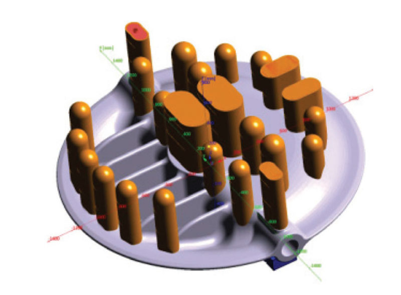
Figure 3 shows the part with a proper feeding system.
The result of the simulation will highlight porosity areas, as shown in Figure 4, which highlights that at least one additional iteration will be necessary to reach the required quality level.
Final analysis and results
Simulating the mould filling phase will allow us to visualise different results such as:
• The temperature during filling, filling time, filling velocity,
• The fraction solid/fraction liquid,
• Air traps,
• Flow tracer.
We can also visualise solidification results, such as:
• Thermal behaviour
• Material status (solid, liquid)
• Hot Spots
• Cooling rate
• Possible remaining defects: porosity, shrinkage, Niyama (micro porosity)

Tips to achieve good results
To obtain sustainable results, you must correctly define various elements. These include:
The materials and the heat exchange within the mould. The foundry ‘s experience of the considered alloys and the casting technique will significantly influence the final result.
The meshing part. Too rough mesh size will lead to poor results, but using a very fine mesh size will increase the calculation time. It can, therefore, be interesting to use different mesh sizes depending upon the areas you wish to analyse.
The casting process. To ensure that the simulatation process reflects reality as closely as possible, the casting process must be modelled by setting detailed experiment plans to identify the various parameters.


Conclusion
To underline the importance of casting simulation tools, it is essential to realise that there is no room for a ‘trial and error’ approach to large-size castings. For example, when manufacturing a DN 2800 valve with a finished weight of 5700 kg, we need to melt and pour at least 12500 kg of melted alloy. Both the cost of the alloy and the melting cost have a significant impact on the global manufacturing cost.


