
Q: I have assembled an apparatus for bench testing control valve performance to make sure that the valve will perform satisfactorily when installed in the process. Could you describe what tests I should perform?
A: I have been retired for some years now. When I was bench testing valves, I performed two types of tests. The first was a static resolution and dead band test. The sticky behavior of valves is often referred to as “Stiction.” It is the result of the interaction between static friction and dynamic friction. Static friction is usually much higher than dynamic friction. As a result, a valve tends to stick in place until enough pressure builds up in the actuator to break the static friction, and then the valve moves quickly to the new position.
Resolution is a measure of the smallest movement in the same direction that a valve is capable of. This is called a “static” test because we always wait long enough after each step for any possible movement to take place. We don’t make any measurements while the valve is moving but only concern ourselves with the valve’s (static) position after it has come to rest. The control signal is stepped in one direction in very small steps. After each step, there is a waiting period to make sure that there is time for the valve to make any move it is going to make before the next step is initiated. Observing the number of control signal steps that are required to make the move tells us how sensitive the valve is, and the term used to describe this is “resolution.”
After several steps in the same direction, the direction of the steps is reversed. Observing the number of steps required to initiate the reversal of valve motion tells us what the “dead band” is. Figure 1 represents a typical static resolution and dead band test.
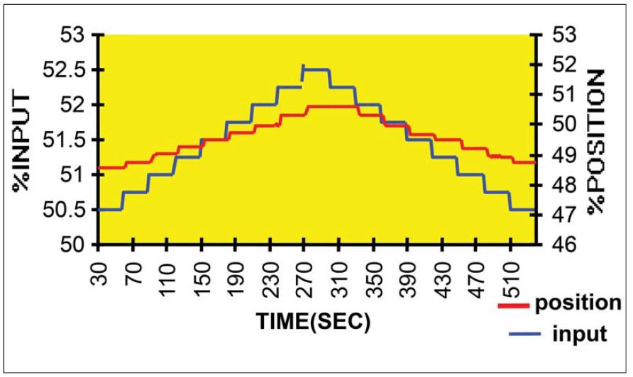
In this example the step size is 1⁄4%. In the same direction, this valve responds to each 1⁄4% step, so it has a sensitivity or “resolution” of at least 1⁄4%. Upon reversal, it took two of the 1⁄4% steps before the valve started moving in the reverse direction, so this valve has a dead band of no more than ∞%. Note that the scales for the input and position are different so that the two graphs will be easier to differentiate from each other. The result of excessive stiction in a closed loop control system is a limit cycle, a situation where the process variable oscillates in a more or less square wave from above set point to below set point. My acceptance criterion for the resolution and dead band tests was less than or equal to 0.5 percent. The second test I performed was a speed of response test. This is a dynamic test because we are concerned with what the valve is doing throughout the test. Figure 2 is a typical speed of response test. My acceptance criteria were based on the recommendation of a process control specialist that I knew at the time.
Fast loops:
- Valve dead time, Td ≤ 20% of desired closed loop process time constant.
- Valve T86 ≤ 40% of the desired closed loop process time constant (this is equivalent to saying that the valve should be 5 times faster than the desired closed loop process response time.)
T86 is defined as the time it takes the valve to reach 86% of it’s final position, including any dead time. - Valve settling time ≤ desired closed loop process time constant.
Slow loops: Not important
Step overshoot: 20% maximum.
Figure 2 demonstrates why the recommended speed of response criteria that I suggest make sense. It meets the requirements for a process where the desired closed loop time constant is 5 seconds. Note that when I talk about the valve response I do not use the term “time constant” because control valve response is rarely first order.
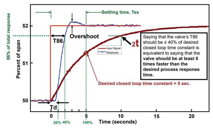
The dead time is just under the recommended 20% of the desired closed loop time constant. The dead time is over in time to have little impact on the overall process response. The valve reaches 86% of its full travel after only 40% of the desired closed loop time constant (T86). The valve is way ahead of when the process needs to reach 63% of its final value, and even farther ahead of when the process needs to reach its 2 time constant (86%) value. Because the valve reaches 86% of its total response in two seconds, and the desired process response should reach 86% of its total response in ten seconds, it is equivalent to saying that the valve is 5 times faster than the desired process response time. At the early stage of the full response, a small overshoot will contribute very little to an overshoot in the process. The valve response has settled to its final value after one desired process time constant, long before the process is expected to reach its final value.
For an in depth presentation of this topic, I recommend reading ISA Standard, ISA S75.25.01 and the associated technical report, ISA TR 75.25.02.
About the author
Jon F. Monsen, PhD, PE, was a control specialist with over 45 years of experience in the control valve industry. He lectured nationally and internationally on the subjects of control valve application and sizing. Jon’s website, www.Control-Valve-Application-Tools.com freely shares articles, training and professional development materials, and Excel worksheets that might be of interest to those who use or specify control valves. Jon passed away in December 2023 and his series of columns is being published in accordance with his wishes.
About this Technical Story
This Technical Story is an article from our Valve World Magazine, February 2024 issue. To read other featured stories and many more articles, subscribe to our print magazine. Available in both print and digital formats. DIGITAL MAGAZINE SUBSCRIPTIONS ARE NOW FREE.
“Every week we share a new Technical Story with our Valve World community. Join us and let’s share your Featured Story on Valve World online and in print.”