
Q: Process controllers play a crucial role in control systems, but their functions and settings can be complex. Could you explain the basics of process controllers in a straightforward manner, without relying on complex equations and graphs?
A: Let’s break down the functions of process controllers and their role in control systems in a simple way:
Controllers are the final part of a process control loop. They compare a signal from a process transmitter, which indicates the actual process conditions, with a desired value. Any difference between the two (an offset) is then modulated, and a final output signal is sent to the control valve (or other final control elements) to eliminate such an offset.
Now, let’s examine the controller settings that modify the offset to create a fitting output signal. (Don’t try to look this up in a handbook on automatic control; you may be confused by the many equations and graphs.)
Here’s my simple explanation:
- Proportional band: This is how your room thermostat operates. All that’s needed is
the setting (the temperature you want) and feedback (the room temperature). You’ll notice that there’s always a small difference between the room temperature and the desired one; that is the proportional band. It’s typically set by the thermostat manufacturer but is adjustable in process controllers. - Rate action (derivative): This controller action is performed when the process (transmitter signal) is above the controller’s set point. Here, the valve is asked to slowly decrease flow.
- Reset action (integral): This correction is made when the process signal falls below the controller’s set point. Here, the valve is asked to slowly increase flow.
All Rate and Reset actions are made in steps per second. Their rate of change may be non-linear, depending on the time constant of the system. A typical diaphragm-actuated control valve has a time constant of 4.7 seconds. This limits the rate of travel to 14% per second, which is too slow for a fast (pressure control) system.
As a rule of thumb, a factor of 3 should separate the Time Constant of a system from that of the control valve for optimum loop stability. This means that with a diaphragm-actuated control valve (without positioner), a controlled system should have a time constant above 14 seconds, meeting most temperature control systems. Note: Proportional band is equivalent to ‘gain’.
Example: To better understand the above, consider this example:
In a heating system comprising:
- A control valve with 1.5 inch travel, controlling the flow of heating medium to a heat exchanger
- A temperature transmitter measuring the temperature downstream of the heat exchanger
- A process controller
When everything is in balance:
- The controller set point is 12 mA
- The transmitter signal reads 12 mA
- The valve is at 50% travel, corresponding to a controller signal of 12 mA
Now, assume there’s a sudden decrease in temperature demand, requiring less flow of heating medium. As a result:
- The transmitter signal drops to 10 mA
- The controller senses this as a 17% error below the set point
- This calls for a rate action response from the controller, requiring a change in the signal to the control valve to reduce travel
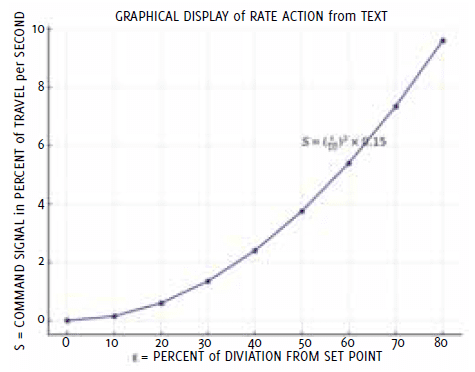
The speed of valve closure is determined by the following equation: S = (percent error/10)2 × 0.15 Where S is the speed of travel in inches per second. In this case: S = (17/10)2 × 0.15 = 0.4 inch per second towards valve closure Assuming the valve has an installed linear flow characteristic, a 17% reduction in flow (and travel) could be accomplished within 0.6 seconds (assuming no dead times in the system).
Conclusion
Understanding process controllers is key to optimising control systems. While the underlying mathematics can be complex, the basic principles are straightforward.
Proportional, Rate, and Reset actions work in concert to maintain desired process conditions. By grasping these concepts, engineers can better fine-tune their systems, balancing these actions to match specific system characteristics and process dynamics. This knowledge forms the foundation for effective control across various industrial applications, from simple heating systems to complex chemical processes.
About the author
 Dr. Hans D. Baumann is an internationally renowned consultant with extensive experience in the valve industry. Throughout his career, he held managerial positions in Germany and France, and his innovative spirit led to the creation of 10 novel valve types, including the well-known Camflex valve. Dr. Baumann has authored 8 books, including the acclaimed “Valve Primer,” and has been granted 115 US patents. He also founded his own valve company, which he later sold to Emerson, and served as Vice President at Masoneilan and Fisher Controls Companies.
About this Technical Story
This Technical Story is an article from our Valve World Magazine, November 2024 issue. To read other featured stories and many more articles, subscribe to our print magazine. Available in both print and digital formats. DIGITAL MAGAZINE SUBSCRIPTIONS ARE NOW FREE.
“Every week we share a new Technical Story with our Valve World community. Join us and let’s share your Featured Story on Valve World online and in print.”