Q: I was recently sizing a control valve for liquid service, and my valve sizing application issued a warning that the noise level was high and that the flow would be cavitating. What can I do to solve this problem?
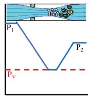
A: Operating a control valve under cavitating conditions will not only result in high noise levels, but damage to the valve internals is also likely to result in unacceptably short service life. One solution is to install a valve designed to minimize cavitation damage. These valves can be quite effective, but they are also much more expensive than standard control valves. Before specifying an expensive valve, you might consider simply relocating the control valve. Figure 1A will look familiar to you, as it is often seen in discussions of control valve choked flow and cavitation.
When the pressure drop across a valve (P₁ – P₂) becomes great enough, the pressure at the vena contracta (the point where the flow stream reaches its minimum area and maximum velocity) drops to the vapor pressure of the liquid, which begins to vaporize. Because the flow rate through a valve is determined by the difference between the pressure upstream of the valve, P₁ and the pressure at the vena contracta, and because the pressure at the vena contracta cannot be less than the vapor pressure¹, further lowering of P₂ does not result in an increase in flow, and we say that flow has become choked. Once the flow stream passes through the vena contracta, the local pressure increases and vapor bubbles entrapped in the liquid collapse generating noise and damaging surrounding valve parts.
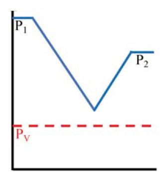
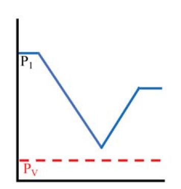
If we were to move the valve upstream in the system as depicted in Figure 1B, both P₁ and P₂ increase, the pressure dip at the vena contracta no longer drops to the vapor pressure of the liquid, and there is no choked flow and cavitation. Another possibility, if the temperature is different at different locations in the process, is to install the valve at a location where the temperature is lower, and the vapor pressure is also lower, as shown in Figure 1C, which may prevent cavitation from occurring.
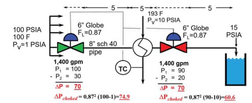
Figure 2 depicts two scenarios and demonstrates the benefits of installing a control valve as far upstream as practical and at a location where the process temperature (and vapor pressure) is lower. At the location downstream of the heat exchanger, the valve pressure drop that would result in choked flow, ΔPchoked, is less than the actual pressure drop meaning that cavitation would be a problem. At the valve location upstream of the heat exchanger where P1 is greater and the temperature is lower, the valve pressure drop that would result in choked flow,
ΔPchoked, is greater than the actual pressure drop, meaning that cavitation would not be a problem.
Reference 1
Tullis, J. Paul, NUREG/CR-6031, Cavitation Guide for Control Valves, 1993.
U.S. Nuclear Regulatory Commission, Washington, DC. Pp 37-38
Reference 1 can be downloaded at: https://doi.org/10.2172/10155405.

About the author
Jon F. Monsen, PhD, PE, is a control valve technology specialist with more than 45 years of experience in the control valve industry. He has lectured nationally and internationally on the subjects of control valve application and sizing. Jon currently hosts a website, www.Control-Valve-Application- Tools.com where he freely shares articles, training and professional development materials, and Excel worksheets that might be of interest to those who use or specify control valves. He can be reached at cvapptools@gmail.com.
