


The storage and transportation of liquefied hydrogen presents many potential hazards, such as leakage and external heat input, that place unique demands on valve designs.
By Naoya Miura, KITZ Corporation, Japan
Liquefied hydrogen – hydrogen which has been converted to liquid – is approximately 1/800th of the volume of hydrogen gas and therefore highly suitable for transportation and storage. Liquefied hydrogen valves are essential equipment in the plant piping systems.
Features of liquefied hydrogen valves
The role of the liquefied hydrogen valve (LHV) is to seal the fluid, which has a temperature of -253°C, the boiling point for hydrogen.
One of the key features of LHVS is a typically long body structure which is designed to prevent the gears from freezing in the cold air produced as the -253°C fluid flows through the valve.
The second key feature of the LHV is the welded connection. As will be explained later, welded connections are used to prevent external leakage of liquefied hydrogen, which would be extremely dangerous.
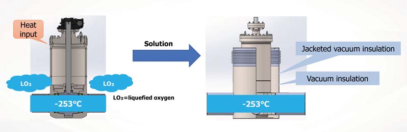
The third key feature of the LHV is the vacuum insulation jacket structure, which serves two main purposes:
- The prevention of liquefied oxygen. Fluid flowing through the valve at -253°C presents a potential danger because atmospheric oxygen outside the valve may be liquefied as the valve cools;
- Preventing heat from entering the valve from the outside. Since -253°C is in the cryogenic region, the liquefied hydrogen would vaporise if heat was to enter from the outside environment.
As liquefied oxygen could also be caused should there be any external leakage of the valve, the LHV is designed with a welded connection to eliminate this possibility. External heat input prevention is necessary to prevent liquefied hydrogen from vaporising due to heat input, which would reduce transport efficiency. The vacuum insulation jacket structure solves these two problems by suppressing heat conduction both internally and externally.
The vacuum insulation challenge
There are two main challenges in establishing a vacuum insulation jacket structure. The first hallenge is heat conduction from the atmosphere to the fluid. As previously explained, it is essential to prevent the vaporisation of the liquefied hydrogen by preventing heat input from the atmosphere. The second challenge is the shrinkage of the accommodating jacket structure due to a temperature difference occurring between the jacket and the valve. Shrinkage occurs when valves are subjected to low temperature conditions, causing stresses in the welded piping. It is therefore necessary to establish a structure that reduces the stresses generated from valve contraction.
Solutions
The first step in defining a solution is to carry out a heat conduction analysis to calculate the amount of heat input to the fluid from the outer surface of the valve. This calculation can be compared with the actual equipment test to improve the accuracy of the analysis method. The establishment of the analysis method makes it possible to design the vacuum insulation jacket structure without having to evaluate the actual equipment.
The second step is the design of the bellows structure. When the valve contracts due to temperature differences, the expansion and contraction of the bellows can suppress the stresses that occur in the piping.
Valve maintenance
If the vacuum in the piping is destroyed during maintenance, the plant restoration process will take a long time. Therefore, the challenge is to establish a structure that allows maintenance of the valve without dismantling the vacuum jacket. To achieve this, the valve must be constructed with a top entry and the valve cover must be outside of the vacuum jacket. Because of these requirements, it is necessary to use a long body structure, instead of a long bonnet structure such as is used for cryogenic valves for LNG.
Summary
Liquefied hydrogen presents many potential hazards, such as leakage and external
heat input. Therefore, it is necessary to prevent external leakage by using welded connections and avoiding external heat input by employing a vacuum insulated jacket construction.
 About the author
Naoya Miura is a member of the KITZ Hydrogen Division, where he is in charge of sales for liquefied hydrogen valves.
He will focus KITZ’s liquefied hydrogen valve sales efforts on the future mass transportation of liquefied hydrogen.
About this Featured Story
This Featured Story is an article from our Valve World Magazine, April 2023 issue. To read other featured stories and many more articles, subscribe to our print magazine. Available in both print and digital formats. DIGITAL MAGAZINE SUBSCRIPTIONS ARE NOW FREE.
“Every week we share a new Featured Story with our Valve World community. Join us and let’s share your Featured Story on Valve World online and in print.”