
The main internal components of a safety relief valve are: disc, nozzle, adjusting ring(s), spring and its supports, guide, disc support, spring adjusting screw, stem, bellows, and manual actuation lever, in addition to the ring lock screw(s).
By Artur Cardozo Mathias
Sealing Disc
 The disc is the movable obturator of a safety relief valve, in direct contact with the nozzle sealing surface when the valve is still closed. This part is housed within the disc support and is exposed to the pressure, temperature, and corrosiveness of the process fluid on its underside and ambient temperature, or to the backpressure and corrosiveness of the environment on its opposite side, inside the valve body.
This exposure to varying temperatures can cause thermal distortions on the sealing face in contact with the nozzle in solid disc designs. These distortions are minimised by the minimal thickness design, allowing for temperature equalisation across the entire disc as quickly as possible.
The disc and nozzle are often made of the same material, but they can also be made of different materials. In this case, the disc material must be harder because it is fully exposed to the flowing fluid. The fluid flow velocity at the nozzle sealing surface is virtually unchanged compared to the velocity at the disc sealing face, due to the disc’s movement during valve opening and closing. The closer the disc is to the nozzle sealing surface, the higher the fluid flow velocity, especially during closing. The most commonly used materials for this type of disc are: AISI 304 (older models), AISI 316, AISI 347, AISI 422, Bronze, Inconel, 19.9 DL (forged stainless steel), or AISI 17.4 PH stainless steel.
The disc is designed to float freely within the disc support, ensuring proper alignment with the guide system and the nozzle sealing surface. An excellent seal and proper seating are possible after the relief process has occurred.
The sealing discs of safety valves operating in boilers or some industrial processes have an integral deflector that has the following functions:
- Directing the flow during the valve opening and closing cycle;
- Protecting the disc and nozzle sealing area from erosion due to the high fluid flow velocity at this point;
- Increase fluid flow velocity, thereby helping to reduce pressure, as occurs with nozzle taper;
- Prevent flow turbulence at the nozzle outlet during the valve’s operating cycle, resulting in rotation of the disc and disc support, which would cause wear on the disc and nozzle sealing surfaces and on the guide surfaces between the disc support and the guide.
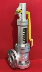
Safety valves operating under high pressures (both in boilers and processes) above 560°F (293°C) can also utilise a special disc design called a flexible disc. In this disc, the fluid’s own pressure and temperature assist in sealing, allowing the valve to operate with a smaller pressure differential between the operating pressure and the set pressure, increasing the efficiency of the boiler or process in which it is installed.
The sealing surface of this type of disc has a certain flexibility, called a thermal lip, caused by the pressure and temperature of the process fluid.
This flexibility increases the valve’s sealing performance, as in addition to thermal flexibility caused by temperature, it also has mechanical flexibility, caused by fluid pressure acting in favor of the spring’s closing force. Unlike conventional designs (solid discs), in which process pressure acts against this force. Thermal distortions on the sealing surface are also eliminated in this design, as the temperature differential is quickly equalized, ensuring a permanent seal.
This type of disc is typically constructed of either Inconel X 718, AISI 347, or quenched and tempered AISI 422. The figure to the side shows a photo of a safety valve with a flexible disc, where the “thermal lip” and the integral deflector can be seen:
This design offers another advantage over the solid disc design, in which the lower tip of the stem, which transmits the spring force to the disc, ends at a value equal to or below the horizontal line of the nozzle sealing surface, providing a distribution of forces concentric to the disc, keeping it centered with the nozzle sealing surfaces, thus preventing vibrations in the horizontal direction.
I are minimized, allowing greater repeatability of the set pressure value, in addition to providing better sealing and ensuring repeatability of the valve closing pressure value.
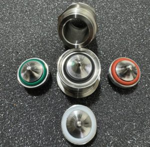
Disc with resilient seat seal
The seal in conventional disc designs can be metal-to-metal or resilient. Metal-to-metal is most commonly used in the case of vapours because the temperature cannot be tolerated by elastomer sealing rings, which are typically made of Viton, Silicone, Kalrez, Buna-N, or thermoplastics such as PTFE. Valves with metal-to-metal seals have lapped contact surfaces to achieve the highest degree of tightness with a small force differential (between the operating pressure of the protected equipment and the valve opening pressure), acting between the internal sealing area of the nozzle and the force exerted by the spring. In valves with a resilient seat on the disc, the nozzle sealing surface must also be lapped. Depending on each manufacturer’s design, part of the force exerted by the valve is absorbed by the metal sealing surfaces between the disc and nozzle, with a small portion of that force being absorbed by the resilient seat.
Safety and relief valves with a soft seat are not recommended for use with steam. Those made of PTFE are recommended only for corrosive fluids and the valve set pressure must be at least 100 psig (7.03 kgf/cm2). This minimum pressure is due to the hardness of PTFE.
A resilient seal is used when maximum valve tightness is desired, such as in the following cases:
- Fluids that are difficult to confine, such as hydrogen, helium, ammonia, compressed air, and toxic gases, among others;
- When the operating pressure fluctuates significantly and approaches the valve set pressure;
- In installations subject to excessive vibration;
- Installations subject to vacuum;
- Fluids containing suspended particles;
- Cases in which ice may form on the sealing surfaces after the valve releases pressure, such as during gas discharge;
- Corrosive fluids;
- Stresses from heavy, poorly supported discharge piping that may cause the valve internals to misalign.
Note: The resilient seat allows for a tight seal even in installations subject to vibration. However, this same resilient seat, in these same applications, does not prevent a reduction in the valve’s set pressure when exposed to excessive vibration.
Seat selection
The resilient seat must be selected according to its chemical compatibility with the process fluid, as well as the pressure limits (according to the nozzle passage area) and temperature supported by the materials. Therefore, the larger the valve size, the lower the set pressure limit. Therefore, if, according to the process flow capacity required, the user needed to select a 6” x 8” valve, with an “Q” orifice (11.05 in2) adjusted to open at 45 kgf/cm2, they would need to specify and install two 4” x 6” valves, with an “P” orifice (6.38 in2), with staggered adjustments.
Nozzle
The nozzle in safety and relief valves, like the disc, is the part that is in direct contact with the fluid, whether the valve is closed or open and discharging.
There are two types of nozzles used: the full nozzle and the half nozzle.
Full Nozzle
This type of nozzle is a rigid stainless steel part that prevents the process fluid from contacting the valve body while the valve is closed and sealing. They are generally internally tapered to increase fluid flow velocity at the outlet, helping to reduce pressure more quickly and minimizing pressure losses at the valve inlet. The inlet is somewhat rounded (usually with a radius of 25% of the inlet diameter), allowing the flow to flow laminarly and directionally.
The nozzle passage area must be large enough to allow a certain amount of flow—the required flow capacity of the process—to be relieved to reduce pressure. However, this required relief capacity should never be less than 30% of the safety valve’s actual flow capacity when operating primarily with compressible fluids.
Semi-Nozzle
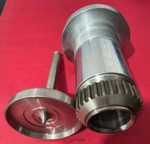
The semi-nozzle is threaded and sometimes welded to the valve body, especially for high-pressure valves. This has a major disadvantage compared to the integral reactive nozzle; In this type, the process fluid, in addition to constantly coming into contact with the disc and nozzle when the valve is still closed and sealing, also comes into contact with part of the valve body. The figure below shows the set of internal components of a pressure relief valve, including the integral nozzle, the nozzle ring, the disc Holder, and the disc with a metal sealing surface: Both the nozzle and disc are typically made of materials Resistant to wear due to erosion or corrosion, and to the high pressure and high temperature of the process. These materials can be rolled or forged in the case of discs. For the nozzle, these materials can be cast, forged, or rolled, depending on the size and design of each manufacturer. The nozzle sealing surface can also be coated with Stellite® 6.
The correct size of the nozzle orifice for a given volume of fluid and at a pre-established set pressure and overpressure prevents the pressure inside the protected equipment from rising to dangerous levels. Therefore, the pressure and volume of the fluid in the equipment can increase until there is a balance between the flow rate being generated in the process and the actual flow capacity of the valve at the moment the relief pressure (set pressure + overpressure) is reached.
Once this balance is achieved, the pressure inside the protected equipment no longer rises beyond the limits permitted by boiler and pressure vessel construction standards. This is achieved when the nozzle throat area is correctly sized in relation to the process’s required flow capacity. In American design standards, the effective nozzle orifice areas are standardised by API Std. 526. In European designs, these areas are standardised by the manufacturers themselves.
The better the nozzle’s internal surface finish, in addition to the other internal components in the flow path, the higher the Discharge Coefficient (Kd Coefficient), and consequently, the greater its flow capacity.
Note: The nozzle area is the smallest cross-sectional area of the nozzle throat (diameter). The valve’s maximum flow capacity is limited by this area and the pressure at which it is set to open.
 About the author
 About the author
Artur Mathias is an Industrial Mechanical and Chemical Technician and a Member of ISA. As a consultant, he has been active since 1985 in the maintenance, inspection, specification, and sizing of valves. With extensive experience in the field, Artur provides training and technical courses to share his knowledge and expertise with others in the industry. He is also the author of the book “Válvulas: Industriais, Segurança e Controle”, which serves as a valuable resource for professionals working with valves in various applications.
About this Technical Story
This Technical Story is an article from our Valve World Magazine, November 2025 issue. To read other featured stories and many more articles, subscribe to our print magazine. Available in both print and digital formats. DIGITAL MAGAZINE SUBSCRIPTIONS ARE NOW FREE.
“Every week we share a new Technical Story with our Valve World community. Join us and let’s share your Featured Story on Valve World online and in print.”