

Recent developments in fail-safe vane actuators are enhancing process control with rotary valves and should be closely followed in the market.
Article by George Wang, President, and Jack Dovenbarger, Head of Sales, Easytork Automation Corporation
___
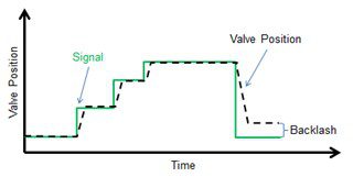
Figure 1
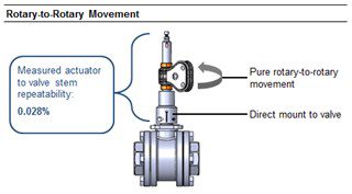
Figure 2
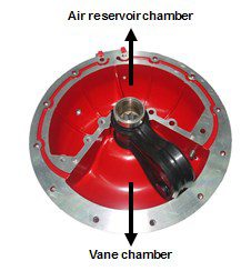
Figure 3: Singular actuator body with an integral air
reservoir and vane compartment. Source: Easytork.
Hysteresis
Hysteresis is predominantly a function of backlash, defined as a loose mechanical part, or the meshing of gears that impart slop between pinions and gears. When reversing direction, the valve movement will be different from the signal (Figure 1). Backlash is unavoidable in all linear-to-rotary actuary designs such as rack and pinion, scotch yoke, and diaphragm rotary actuators, as these designs require a mechanical pinion to convert linear generated force to rotary force. Regardless of the quality, the pinion is a wearable part that results in increased backlash over time. Unlike linear-to-rotary, vane actuators are pure rotary-to-rotary, meaning all motion produced by the vane actuator transfers unfiltered to the valve stem with zero motion loss.
Until recently, vane actuators were not designed to direct mount to valves and almost always required brackets and couplings for linkage to valve. Note that brackets and couplers are intermediary mechanical components that result in backlash. This historical limitation of vane designs requiring brackets and couplers has limited their use for control valves. Therefore, the ideal actuator for control valves is a vane actuator that can direct mount to valves. The good news is there have already been advancements in this direction. In recently conducted tests, the actuator and its linkage to the valve system added only <0.05% repeatability to the control valve system (Figure 2). Unlike linear-to-rotary actuators, where the pinion experiences wear and lost motion which leads to increased backlash over time, rotary-to-rotary designs do not have to contend with the increased backlash of the pinion.
5/2 fail-safe to optimize process control Additional variables that affect process control optimization include stiction, size limitation, stiffness, response time, safety, and actuator life cycle. Process control optimization can be achieved if 5/2 systems are used instead of 3/2 systems. The former refers to the air flow used in actuators without springs, e.g., double-acting. The latter refers to the air flow used in actuators with springs, e.g., single-acting. In particular the incorporation of springs hampers decision makers with trade-offs among better process control optimization, size, cost, non-linear torque curves, and cycle life. With springs, actuators must be upsized to overcome the spring tension, which leads to increased cost. Additionally, a spring-return vacuums atmospheric air and particles into the actuator housing, damaging the actuator’s spring and soft sealants and resulting in a reduced cycle life on an expensive component.
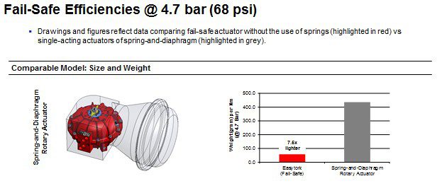
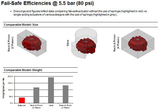
Thus, the ideal solution on a fail-safe requirement is fail-safe on a 5/2 system. Again, this solution already exists. Air reservoirs can be used in the fail-safe mechanism, as traditionally seen in actuating large shutdown valves, or large process control valves. With the proper pilot assembly, the reservoir is constantly pressurized and available to perform the failsafe operation during a power loss, control signal loss, or catastrophic air failure. Reservoirs have traditionally been external to the actuator. This arrangement not only adds size, weight, and cost to the system, but also requires a considerable amount of external tubing and mounting hardware. These considerations increase the overall footprint, limiting the actuator’s usefulness and cost efficiencies. The ultimate design – and one already design, built, and field tested – integrates the reservoir into the pneumatic actuator housing to provide the necessary stored energy for fail-safe (Figure 3). Without the need for external hardware, these new-generation actuators are the smallest, lightest, and least airconsuming fail-safe actuators on the market (Figures 4 & 5).
– Stiction and actuator size
Stiction is the resistance to the start of motion, and any amount of stiction degrades the performance of the control loop through a stick/slip cycle. The general prescription for preventing stiction is to use a stronger or larger actuator to overpower the system’s static and dynamic friction. However, this is often not possible, due to the size and cost of a larger actuator system. The introduction of a fail-safe actuator with an internal reservoir effectively addresses this concern.
Another factor impacting the size of spring-control actuators is that they generally only provide about 35% of their original double-acting torque output. The majority of the actuator’s potential energy is used to compress the spring, so in order to get the same output torque to the valve, the actuator needs to be drastically upsized. Fail-safe actuators with reservoirs, on the other hand, do not compress against springs, which means all generated torque goes directly to the valve system. Easytork’s internal reservoir fail-safe actuators, for instance, retain 60% of their double-acting configuration at the fail position end-of-stroke. Compared to a spring-return, air reservoirs can utilize, by a whole magnitude, smaller actuator bodies with lower air consumption and less weight (Figures 4 & 5).
– Response time and air consumption
The efficiency of an actuator’s air consumption directly affects its response time. When the positioner needs to fill less air volume to achieve the same output torque, the response time improves. Vane actuators use the least amount of air volume per torque. On double-acting, a pear-shaped vane utilizes about 110% less air volume than a rack & pinion and drastically less air volume than a diaphragm rotary actuator. Combined with the high handling pressure of vane actuators, actuators can achieve stroke times of <0.5 seconds for torque requirements of 1,800 in-lbs. The challenge, then, is to find a positioner capable of matching the capability of the actuator.
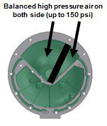
Figure 6.
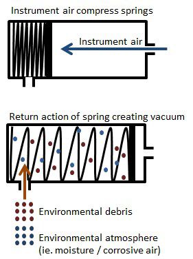
Figure 7.
– Stiffness
As the dynamic force of a flow fluctuates, the control valve must remain in the same position as dictated by the controller. To do this, the valve is dependent upon the actuator stiffness to minimize these position fluctuations. When a springcontrolled actuator is operated near its fail position, reduced spring potential energy coupled with the sudden change in dynamic force can cause the valve to slam shut.
The stiffness of a 5/2 fail-safe actuator is significantly greater than that of a springreturn actuator. In 5/2 systems, there is balanced pressure on both sides of the actuator vane/piston, which provides for exceptional stiffness and precise throttling control. Furthermore, vane actuators can handle up to 150 psi supply pressure, whereas throttling diaphragm actuators are limed to 30-60 psi, decreasing their torque-producing capability. The high stiffness helps the actuator withstand sudden changes in dynamic fluid force acting on the valve trim, and provides better resistance to slamming shut on small openings (Figure 6).
– Lifetime cost
After addressing all process control optimization variables, the most important factor is the cycle life of an expensive component. Regardless of build quality or actuator design (diaphragm, scotch yoke, rack and pinion, vane), all spring-return 3/2 actuators will have varying degrees of spring issues. These can include spring fatigue and broken or corroded springs. Again regardless of the design, it is inevitable that all spring-return action will vacuum in atmospheric environment and particles into the actuator. This exposes parts to corrosion and can damage the actuator’s soft sealing (Figure 7). 5/2 air reservoir fail-safe designs, on the other hand, negates this problem, as there is no spring to vacuum the environment into the actuator. On the contrary, these actuators will always push instrument air out of the actuator.
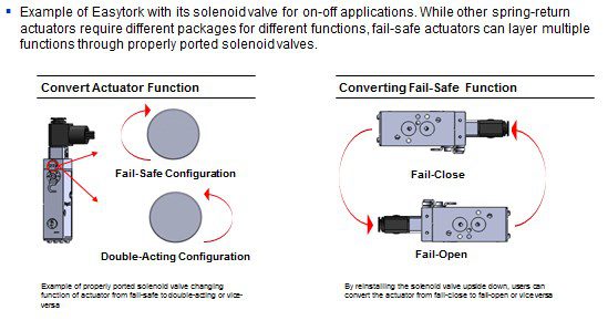
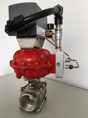
Figure 9.
Safety and ease of functionality change
Fail-safe that doesn’t require springs increases safety. When someone changes the functions of actuators by inserting or re-orienting springs, his or her proximity to the springs directly exposes them to dangerous amounts of potential energy. Injuries and deaths have resulted, especially with larger springs. Spring-less fail-safe also simplifies businesses’ overhead costs, particularly when it comes to labor and inventory variety. Significant labor time is spent changing the function of the actuator. Corporations must therefore purchase and stock each actuator function (double-acting, single-acting in fail-close or fail-open).
Fail-safe with air reservoirs resolves all these considerations. There is no hazard associated with springs, so converting the functions of this type of actuator is as safe and simple as re-orienting the solenoid valve, re-piping, re-programming the position, etc. None of these activities exposes personnel to the dangers of springs, as there are none to begin with.
Converting an actuator from fail-close to fail-open simply requires turning its solenoid, or pilot valve, upside down or reprogramming the positioner. This is done without touching the actuator or removing the system from the line (Figure 8). All the functionalities an actuator requires are already pre-built into a singular out-ofthe- box actuator, coupled with the speed and simplicity of achieving the required functionality. This also drastically reduces labor and inventory overhead.

George Wang

Jack Dovenbarger
The new frontier
A vane actuator with an internal air reservoir that can direct mount to valves offers the process control market new technical possibilities that were once unattainable or too economically prohibitive. These features have been designed, built, and field tested with positive results (Figure 9). Advancements in actuators offer valve and positioner manufacturers an opportunity to expand their own solutions to fully utilize this new generation of actuator’s capabilities. The combination of these advancements is bringing about a new frontier in process control optimization.
About the authors
George Wang
George is president of Easytork Automation Corporation. Prior to founding Easytork, George was part of the group that founded Taiwan Ball Valve, one of the larger ball valve manufacturers in Taiwan that was sold to Tyco in 2002. That same group created and patented the design for Easytork. Formerly an investment banker at RBC Capital Markets with a focus in the industrial segment, George received a degree in finance and accounting from New York University’s Stern School of Business.
Jack Dovenbarger
Jack is head of sales at Easytork Automation Corporation. Previously, Jack was vice president of product development at K-Tork, product development manager at Rotork and national municipal sales manager at Kinetrol. Jack’s experience in the valve automation arena encompasses pneumatic, electric, hydraulic and electro-hydraulic automation.