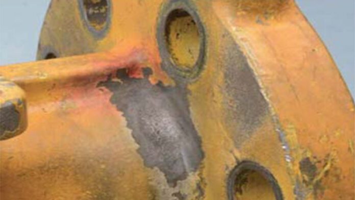
After shrinkage was identified in a high-nickel-alloy body after a change in gating pattern, it was clear that the well-established, industry standard RT angles were unable to adequately show all casting defects.
By Marshall Norris, Dennis Baker and Keith Walker, Flowserve Corporation
Flowserve provides equipment for use in severe services in the petrochemical industry, including to several organizations involved in oil refineries. During the refinery process, hydrofluoric (HF) acid alkylation (alky) is used to convert isobutane and alkenes into alkylate, which is used to make gasoline. HF acid is a highly hazardous substance, and even limited human contact with it can result in severe osteonecrosis or death if not treated immediately.
Because of the risk involved, valves that are used for this service are subject to a high degree of verification, including pressure testing, material verification, and radiographic inspection (RT) to verify that cast components do not contain porosity, voids, inclusions, cracks, hot tears, or shrinkage. ASTM E446 governs the methodology for identification and disposition of the results of RT in cast components with a wall thickness of up to two inches, a category many of Flowserve’s valves fall into. Flowserve takes additional measures for in situ detection of leakages using a reactive yellow paint that responds in red discoloration in the presence of HF acid.
Leaking valves at HF alky unit
In May 2021, the Flowserve Cookeville (CVO) facility was contacted by an HF alky processing unit and informed that a three-inch class 300 Monel valve had been identified as leaking after being in service only a couple of weeks.
The facility shut down the line and followed procedures to contain any process media before human or environmental exposure occurred. The leakage occurred through the valve body wall at the top of the valve where the flange meets the neck (as shown in Figure 1), and Flowserve launched an investigation to identify the root cause for the leakage. Within the month, the alky unit identified two additional valves with body material from the same heat that also began to leak in the same location.
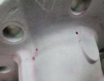
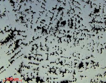
The investigation identified the root cause of the leakage as shrinkage (Figure 2) that was not identified during RT examination. vUpon the investigation’s completion, it was determined that the RT views used to verify casting integrity were insufficient to capture the problematic area. At that time, Flowserve revised its requirements for areas of the valve requiring RT inspection. Concurrently, the customer also hired a third party that launched its own investigation and identified shrinkage in the area where leakage was identified by lining the inner diameter of the valve ends with film as shown in Figure 3.
Flowserve’s RT supplier was able to orient the valve body at an alternate angle that revealed the previously hidden shrinkage location. Following a corrective action by Flowserve, an update of the procedure and drawing for the locations for RT was sent to the customer, and the root cause of the escape was deemed identified.
At that time, Flowserve also requested the foundry perform numerical analysis to determine if the shrinkage could be predicted.
A second irregularity
However, in November 2021, before the numerical study was completed, a second HF alky unit contacted Flowserve after having identified a leakage on a four-inch class 300 valve on the same feature, but this time, the leak was at the bottom of the valve flange to neck connection. Once again, the valve had been in service only a couple of weeks, and another investigation was initiated to identify the root cause. During this investigation, leakage was reported on a four-inch class 300 valve at another HF alky unit.
However, unlike the first two leaking valves, this instance spanned more than one heat. Flowserve issued a warning on all valves from the foundry to investigate whether there was a problem with all the valve bodies produced there. Flowserve’s RT supplier re-evaluated the valves and identified shrinkage forming tunnels across the pressure boundary. However, the shrinkage found was determined acceptable in accordance with level 2 shrinkage acceptance guidelines specified in ASTM E446.
It was suggested that if microporosity was not identified by Flowserve’s standard pressure test, the use of helium detection by means of mass spectrometer would have the resolution to determine micro tunnels in the material. Helium testing was performed on the valves and additional leak paths were found that had not been rejected after RT re-evaluation.
However, Flowserve found that some leak paths were still masked at the recommended 50 psi for 30 minutes and leakage was not detected until the valve bodies were pressurized to 300 psi. In some valve bodies, shrinkage was identified by RT but could not be detected via helium testing, and in other cases, the reverse was found. It was determined that all future valves would be tested via both RT and helium testing.
Root cause
A recent change in supply chain from a sand casting-based foundry to a new investment casting-based foundry had caused the gating on the patterns to be revised. Flowserve’s casting experts suggested that the new method was the cause of the appearance of the shrinkage in the bodies.
The foundry recommended that additional material in the leaking area would mitigate the shrinkage, but upon a first-piece destructive inspection (shown below in Figure 7), the foundry still found micro shrinkage in the area of interest. The shrinkage, however, was still determined acceptable as level 2 per ASTM E446. The gating was reviewed by Flowserve casting experts and based on the previous gating of the sand castings, they recommended a change to the gating path.
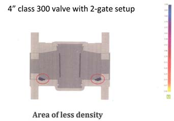
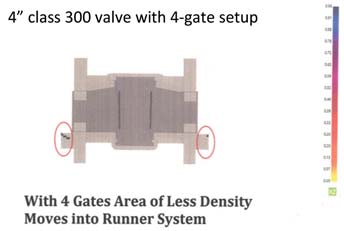
Using a finite element software platform procured by the foundry, the old gating pattern was evaluated, and shrinkage was predicted in the location the leakage was observed (Figure 9). The pattern was then updated and re-evaluated, at which point the simulation predicted no shrinkage. The redesigned gating location is shown in Figure 10.
Upon confirmation of the relocation of the low-density areas, the foundry successfully repoured the valve bodies with the new gating pattern, followed by RT and helium inspections to verify the updated gating pattern effectively mitigated the shrinkage observed in the current valve bodies.


Conclusions
Shrinkage was identified in a high-nickel-alloy body after the gating pattern was changed. The well-established, industry standard RT angles used were unable to adequately show the casting defects in areas of interest, and it is recommended that valve and pressure containment equipment manufacturers re-evaluate the required views for RT, especially when there is a change in process or supplier.
The results of the RT showed acceptable levels of shrinkage (Level 2 or better) per ASTM E446 but did not adequately reveal the risk of leakage due to shrinkage creating tunnels across the pressure boundary. Helium testing was highly effective in identifying leak paths across the pressure boundary but only after being pressurized to 300 psi. Finite element software was used to accurately predict locations of concern and redesigned gating was used to ultimately address the root-cause casting issue.
