Water leakage and burst pipes are mainly the cause of overpressure. The higher the pressure, the more water is pushed through leaks in the pipes. In Denmark, several companies and organisations addressed the issue and tested intelligent pressure control systems to lower the (differential) pressure. The goal: to reduce water leakage, the occurrence of burst pipes, while guaranteeing service levels to the water users.
By Michael Ramlau Hansen Public Affairs AVK Holding A/S
AVK Valves worked together with two Danish water utility companies, HOFOR and NOVAFOS, on a publicly funded project named Leakman, see box text. Both companies employ traditional pressure control management, performed by adjusting the control valve to a specific downstream pressure. This valve has been designed to keep the pressure constant, regardless of any other impact such varying upstream pressure, or varying level of consumption of water. As long as the upstream pressure is higher than the predefined downstream pressure, the downstream pressure will remain stable. The valve does however require a certain differential pressure (the difference between upstream pressure and down-stream pressure) to regulate in a stable manner, which became quite the challenge for HOFOR.
Fluctuating pressure
First, some elementary insights regarding flow. The sum of supplied energies remains constant. This means that if flow rises, pressure lowers and vice versa. If the flow is reduced, the pressure rises. In a water distribution pipe network, there is a kind of buffer, a delay in the pipes. Immediately after the pressure control valve, the pressure is constant, but at the other end of the section which may be miles away, the pressure will fluctuate according to the consumption level.
A typical daily water consumption routine in the distribution grid shows higher consumption in the morning and evening when people bath, make their coffee, cook, do the dishes and other household activities. During the daytime much less water is spent as people are at work and during the night when everybody is asleep.
Pressure reduction, less water loss and pipe
 As mentioned, water consumption, or flow, impacts the water pressure in the section, meaning that the pressure rises and falls during the course of the day. Due to leakage, this is not desirable, but the varying pressure also impacts the lifespan of the water pipes negatively. They are subjected to stress which causes pipe ruptures followed by serious leaks and water loss, not to mention the collateral damage caused by serious pipe bursts.
If pressure can be reduced by, say 10 per cent, the amount of water lost will also reduce by10 per cent. As for the occurrence of pipe bursts, a reduction of pressure of 38 per cent will reduce the pipe burst frequency by 53 per cent (Lambert A. and Thornton J, 2007). In a parallel fashion, calculations show that a pressure reduction of just 1 per cent will prolong the lifespan of the pipe network by 0.2 years.
The task at hand is to turn this upside down by keeping the pressure in the section constant while the pressure immediately after the pressure reducing valve varies according to consumption. We call this Demand-Driven Pressure Management.
Compare flow
To make control of a pressure reducing valve automatic rather than manual, the valve must be fitted with electronics that allow communication with the surroundings.
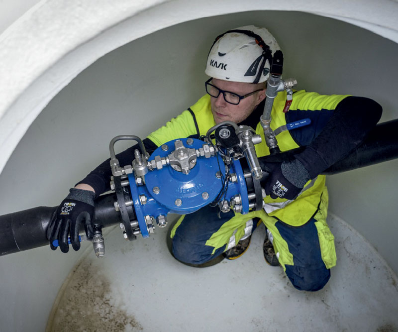
This illustration is a blueprint of an ‘intelligent’ pressure reduction valve as it will look in the inlet chamber of a supply section. The control unit ACMO PMD receives a signal from the flowmeter and a pressure sensor placed on the downstream side of the valve.
This way, the control unit can compare the flow to the pressure and adjust the opening port of the control valve. The signal from the pressure sensor on the upstream side performs two functions. Its main purpose is to provide the input that controls the speed of the reaction of two solenoid valves.
The higher the inlet pressure is, the quicker the reaction must be as the inlet pressure is used as the power that makes the control valve turn towards an open or closed position.
Keep constant pressure
Furthermore, the pressure sensor works as a security mechanism via communication with the SRO system. If the upstream pressure falls below the setpoint of the downstream pressure while the control valve is completely open, this can be caused either by leakage or by a fault in the pump that delivers the upstream pressure. By reporting ‘low upstream pressure’, the water utility should look for a faulty pump rather than a leaking pipe in the section.
It is also possible to build a function into the SRO system which regulates the pressure in steps according to the flow within predefined intervals. This means that the valve can maintain a constant pressure at a critical point (a critical point is defined as a point in the section where supply of water is essential, e.g. a hospital, a water consuming industry or a high-rise building) of the section which makes a successful outcome far more likely compared to the pressure fluctuations described above.

LEAKman
The tests that were conducted at NOVAFOS and HOFOR were conducted under the auspices of the LEAKman project. This initiative has been established to demonstrate Danish solutions for limiting drinking water loss and pave the way for new technology.
The LEAKman project intends to establish guidelines for selecting the proper tools and techniques to be implemented at water utilities worldwide in order to reduce the NRW level to a specific target level. It will include several vital aspects such as economic analysis of the return of investment (economic level of leakage), selecting appropriate KPIs for targets and monitoring of effect of different leakage manage-ment solutions and the implementation of interfaces between the systems.
Varied set-up
As mentioned above, the tests were conducted at two water companies – NOVAFOS and HOFOR- respectively at two locations, at Klampenborg and Mileparken, both suburbs of the Danish capital Kopenhagen. Both companies have divided their distribution grid into zones or DMA’s (District Metered Areas).
The setup varies somewhat as the supplies had a wish that the software of their control, the SRO systems, were involved. In practice, this means that all information from the section is routed through the SRO systems to the pressure reducing valve.
Also, in the Klampenborg section, there are two active inlet chambers (always open) and an emergency inlet which is always closed but which can be remotely controlled and opened in case of fire near buildings of particular architectural or historic interest.
The pressure reducing valves in the two active inlet chambers are fitted with small solenoid valves (see blueprint above) that are controlled from the SRO system. The solenoid valves trap a small amount of water in a chamber where the water pressure works through a membrane, with the higher inlet pressure on one side of the membrane and the lower outlet pressure on the other side of the membrane. The differential pressure is used to open, shut or adjust the opening slot of the valve, thereby regulating the pressure loss across the valve and maintains the downstream pressure.
Danger of getting stuck
As a result of this construction, no 230-volt or 400-volt power supply is required – a simple 24 volt to the solenoid valves suffices. The standard version is equipped with a hydraulic pilot valve which does not require power supply at all.
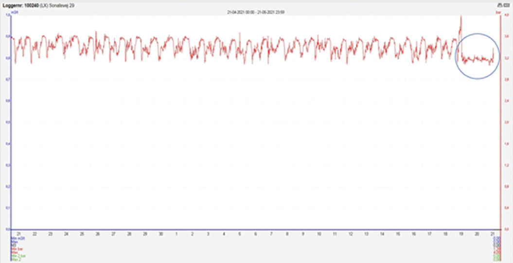
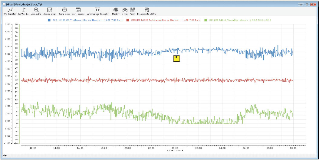
The activity level of the two solenoid valves is rather high, as they will constantly try to maintain the set downstream pressure regardless of impact of the external flow and/or pressure. In addition to the construction of the control function, this was a parameter the water utility wanted implemented in the control. This caused some problems as a completely open valve loses its differential pressure and hence its ability to move toward the closed position, and so the valves would become stuck in an open position without the option to regulate. When the pressure of a supply section is stabilised, such as can be seen on the graph below, fluctuations of pressure become easier to spot. Sudden pressure peaks are easily spotted, enabling the water works to analyse the situation and find the cause of the pressure peak.
Standard solution ‘custom made’
In the Mileparken section, a hydraulic pilot has been used to control the pressure reducing valve instead of the solenoid valves. This is AVK’s standard version. The hydraulic pilot works through a membrane with downstream pressure (water) on one side, and spring pressure on the other side. The spring pressure is adjusted according to the desired downstream pressure thereby maintaining a constantly balanced downstream pressure. If a different downstream pressure is required, the impact of the spring must be changed through a simple handle, tightening or loosening the spring force.
This configuration does not require power for controlling and so the option of “over-riding” like in Klampenborg is not available. In Mileparken, however, there is a requirement that the downstream pressure must be controllable through HOFOR’s SRO system. This requirement caused AVK to enter a cooperation with AUMA to find an electric actuator which, through the SRO system, can control the spring pressure remotely.
We found a solution with an AUMA Profox actuator with Profibus communication mounted on the standard valve. This configuration only requires power a few times a day when the SRO system requests that the actuator change the spring pressure/outlet pressure. If the power supply fails, the valve will continue to adjust according to the setting that was prevalent at the time of the power outage.
Learning Points
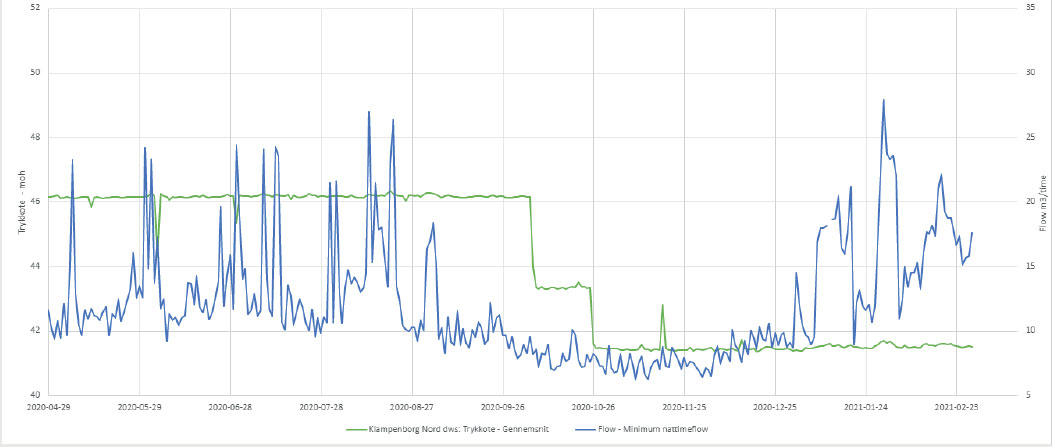
At both locations, the water utility companies were able to lower and maintain the (differential) pressure. It is important to note that sufficient differential pressure is needed across a control valve as the control function becomes rather poor at a low or non-existing differential pressure.
We saw this at Novafos. When the non-self-actuated valves did not shut at a decreasing flow, the valves lost their differential pressure and so their ability to regulate. Had the valves at Novafos been an plunger valve type, the valves could have been adjusted through an electric actuator with a direct connection to the seating.
Small steps
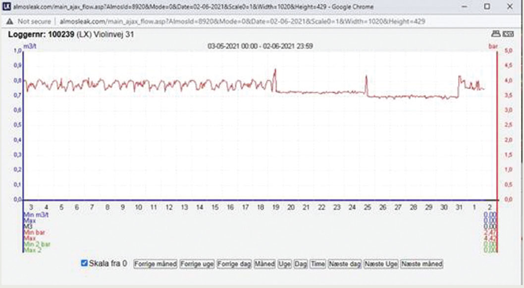
Another finding was that both companies were able to continue their service levels with a decreased water pressure. A few years ago, NOVAFOS attempted to lower the pressure of a given section. This was done in just one the same reduction which caused various complaints of lack of water. The water was actually there but the psychological factor when the tap let out less water than previously was cause for complaints.
With the new design, NOVAFOS was able to reduce the pressure in small steps while monitoring the pressure in the remotest part of the section to ensure it did not fall below the service pressure. Thus, the pressure was lowered without a single complaint and without affecting consumption levels.
Whether the pressure control has had a positive effect on the leakage rate or the pipe burst frequency? This cannot be unequivocally and positively stated due to the mentioned impacting factors. However, as stated before, it can be assumed that pressure reduction and a stabilisation of pressure is likely to lead to less water and less pipe bursts.
About this Featured Story
This Featured Story is an article from our Valve World Magazine November 2021 issue. To read other featured stories and many more articles, subscribe to our print magazine.
“Every week we share a new Featured Story with our Valve World community. Join us and let’s share your Featured Story on Valve World online and in print.”


