

^ Optimised design of flanges and gaskets allow for more efficient and smaller solutions in high-pressure systems
Article By Sriram Nair
___
Flanges constitute a very important part of a pressure containing system (HPS) which will permit their disassembly for maintenance and later modifications. These flanges are adopted in most pressure vessel and piping system due to its favorable geometry. Flange joint assemble mainly falls in two main categories namely bolted joints and pressure actuated joints. The difference between the two are how the pressure load is resisted and a leak tight seal is achieved. Gasketed flanges are widely used in systems under internal pressure as well as other loadings.
It gets complicated on the high-pressure applications as much as 20000 psi which is now fully standardized by API specification for the well-head equipment. These flanges are much lighter and smaller with less bolts. Even though its being constructed with the rules governed by ASME, the careful analysis of the design criteria must be evaluated for flanges of various pressure loads and various materials.
The ASME and API codes differ in the material, hydrostatic-test, and nondestructive-examination (NDE) requirements. The API codes provide temperature derating factors for elevated temperature design. Additionally, the hydrostatic-test pressure in ASME varies between divisions and has also fluctuated over time because of the experiences of the ASME community.
General flange design
General flange design method
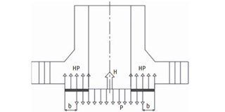
The ASME VIII Div.1 Appendix 2 provides the “Rules for Bolted Flange Connections” with ring gaskets. What the rule provides is, simply the calculation of minimum required bolt area. It considers the two force components as described by ASME, Wm1 & Wm2 which are basically the pressure induced force and compressive force to seal the gasket during assembly of the flange joint respectively. The Wm1 comprises of two loads,
- A compressive force to counter the distributed load due to pressure during operation. The force H simply the internal pressure but equating H using the pressure diameter “G” which is larger than the bore. The equation assumes that the pressure will pry open the sealing faces which makes the pressure area wider than bore.
- A compressive force to seal the gasket. This considers the perimeter of the gasket. This also considers the gasket factors “m” which is the experimental value described by ASME to ensure required contact pressure.
The Wm2 is the force required to seal the gasket during assembly equating the area of the gasket with a gasket factor “y” which is a minimum design seating stress of the gasket as described by ASME. Once the WM1 and the WM2 are equated, the rest of the calculation is to find out number of bolts required based on the root area without exceeding the allow able stresses and the flange moments & stresses to determine the thickness of the flange.
High pressure flanges
High pressure flanges
In the aforementioned flange design method, on a high-pressure application with the ring gasket, the separation occurs at the flange bore. The amount of separation depends on the stiffness of the flange and amount of bolt preload this in return reduces fatigue due to cyclic loading on the other hand, such flanges require more bolting thus increasing the overall size of the flange.
Several design criteria have been derived and some are developed by the Standardization Committee of the Association of Well Head Equipment Manufacturers (AWHEM), for 15,000 and 10,000 psi working pressure, and later adopted as standard by the American Petroleum Institute (API). Several papers and notable papers like ASME paper No. 57-Pet-23 and ASME Paper No. 63-PET-3 provides the design criteria for such high-pressure flange designs. The rules from the ASME VIII provides the base for a proper flange design. The later has been modified in a convenient way in “Modern Flange Design” by Taylor Forge.
CFJs
In contrast, the development of the compact flanges or CFJs emerged which is lighter and smaller in size. The CFJs, as described in the paper by Finn Kirkemo, have a tapered face and an elliptical transition at the back of the flange face instead of a hub to obtain low stress concentration factors (SCFs).
The assembly uses a self-seating and pressure-energized gasket. This provides possibility to design for zero separation or limit the separation based on the characteristics of the seal ring since the major sealing force is applied where it is needed. With a predetermined bolt stress, the flanges are placed in a controlled metal to metal contact as a result the bending stress at the hub is reduced and the flange separation is eliminated. These are adopted and standardized by the NORSOK but only limited to 2500lbs.
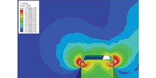
Preload gasket stress. Image courtesy:
API HPHT FLANGE DESIGN
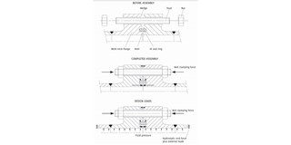
Working of Norsok compact flange with IX
gasket. Image Courtesy: NORSOK L005
Pressure-energized gaskets
The development of self-seating and pressure energized gaskets namely the BX type ring gasket played important role reducing the flange sizes. With reference to ASME Paper No. 57—Pet-23, the gasket width is independent of the bolt load which seals at the outer sealing flank in the grove. The gaskets are so designed that sealing takes place along small bands of contact between the grooves and gasket OD. The gasket is made slightly larger in diameter than the ring grooves.
It is compressed slightly to achieve initial sealing as the joint is tightened. During the initial bolt up condition, the flank contacts the groove with the flange standoff of 1/8” and further tightening of bolts will position the gasket slightly on the groove flanks with the flanges face to face.
The BX type has a pressure equalizing hole drilled through the gasket parallel to its axis to equalize the pressure formed in the pockets since both the ID and the OD of the gasket may contact the grooves. Several modified gaskets are also developed for instance the Cameron type AX and CX have also adopted similar design methodology.
The design allows face to face contact between the hubs to be achieved with minimal clamping force.
About the author
Sriram Nair (Mechanical Engineering) is the technical Authority at Merwede Valves, The Netherlands. He leads the Engineering and R&D-department. Merwede valves celebrating its 70th year of manufacturing specialized nonstandard valves for severe services and high-pressure applications.

Conclusion
The pressure energized gaskets and flanges are smaller than its counter parts with a regular ring gasket. Most of these joints utilize non-load carrying self-seating pressure energized gaskets. With years of experience and established rules from ASME, the API 6A which utilizes self energized gaskets, has proven its optimized design and with innovation in the gasket design and ways to dissipate the flange stress like CFJs, flanges have now become and could be smaller and efficient for more demanding high pressure systems.
References
- ASME, Boiler & Pressure Vessel Code, Section VIII, Division 1 and 2
- ASME B16.5, Pipe flanges and flanged fittings.
- ASME Paper No.63-Pet-3
- ASME Paper No. 57-Pet-23
- API Spec. 6A, Specification for Wellhead and Christmas Tree Equipment.
- Modern Flange Design – Taylor forge
- Design of compact flange joints – ASME PVP 2002
- NORSOK L-005