In 2021, the new Technical Instruction on Air Quality Control act (German: TA-Luft) came into action. It impacts other European Nations as well, because gasketing materials often are specified with regards to this technical instruction within customer chemical and petrochemical plants worldwide and across Europe. This article is part 1 of a series of articles.
By Ralf Kulessa, ESA Flange Gasket Division
TA-Luft can be regarded as ‘rule’ for allowed fugitive emissions: a list of media which either are dangerous to the environment, to human beings, or are expected to be dangerous – for example because they are changing the genetic material or are even intolerable such as dust or smell, even if they are not directly toxic.
The TA-Luft ‘list’ currently spans 700 pages. It lists several media, and for each of the media, there is a limit given which is considered to be ‘non-toxic.’ Fugitive emissions, transportation, decanting, storage of medias (liquid, gaseous, noise, dust,…) are treated within this technical article, where it will be explained how to follow the rules of the air pollution control act, which is legislative, and therefore can be considered to be treated like a law as well.
Only in Germany, the instructions of the TA-Luft must absolutely be followed. From a gasketing perspective, chapter 5.2.6 is the most interesting, because it includes fugitive emissions, transportation, decanting and storage of media with its sub-chapters:
- Pumps and Rotators/Agitators, Valves (5.2.6.1).
- Compressors (5.2.6.2).
- Flange joints (5.2.6.3) clamp connections (Tri-Clamp connectors).
- Shut-off devices, Control devices (5.2.6.4), Compression packings.
New rules for flanged joint connections
According to the ‘old’ TA-Luft, a certificate showing the result of a standard test setup could be used for the gasketing material. Metallic connections, which contain a medium listed in the TA-Luft paper, now have to be calculated in accordance to DIN EN 1591- 1, using DIN EN 13555 characteristics.
The outcome would be a range of possible torque levels with a given sealability level (L0,01) where the iterative calculation is done, checking tolerated strength of flanges, screws and gaskets as well as bending of flanges, local plastification of materials and recovery using actual (on-site) given temperatures and pressure conditions in working and mounting situations, for all components of the bolted connection.
If no numerical iterative calculation or no finite element method (FEM) is possible, a test rig setup still can be done, as well as other methods like FEM analysis.
The ‘old‘ test-setup
Until now, the test setup was always done with a pair of standard steel flanges, including standard sizes of DN40-PN40 related to DIN EN 1092-1 and the gasket geometry was the same size related to DIN EN 1514-1 DN40 PN10. The measured sealability class was done with 1 bar and should meet the criteria of 1,0 x 10E-04 [mbar*l)/(m*s)].
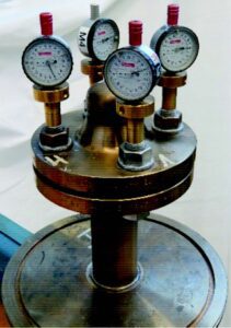
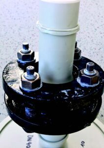
The ‘new’ test-setup
Most likely, all kind of ‘low-load’ flange connections, such as PVDF, PE/PP, FRP or glassy connections (enamel), cannot be calculated using the above calculation methods, because they do not perform linearly on temperature changes.
Especially, if the customer purchases same-size components from different producers, all plant owners now must do the new test setup for each size and each component they purchase/source. For ‘low-load’ flanges, each nominal flange size and even each pressure number often are produced with different flange thicknesses or made in different ways using different production methods from each flange producer. This means that each producer and each size must be checked with the new given test rig-setup, using:
- The respective working conditions like temperature and pressure.
- The respective clamping components like screws or loose flanges.
- The respective (different) gaskets and flanges (from different producers).
The ‘new’ measurement unit also has changed. Reading the numbers, this seems to be easier
to fulfil, but the truth is different, because the ‘old’ unit used to be a volumetric unit and the new unit now is a weight-based unit, where single atoms of the test gas helium are counted using a helium mass-spectrometer.
The new criterium is 1,0 x 10E-02 [mg/(m*s)]. This means a gasket with a circumference of 1m is now allowed to have a ‘leakage’ 0,01mg per second. This is regarded to be sealability class L0,01. Because now, the new test pressure always is the true working pressure (and sometimes can be 40 bar or even 100 bar) it even is harder to fulfil, because more atoms are passing the gasket on higher pressure levels.
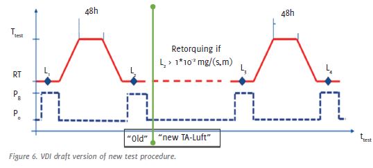
The “new” test-procedure
Difficulties of sinking into surface
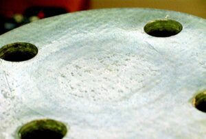
All gasketing materials used on ‘low-load’ flanges (except glassy surfaces) are at risk of ‘sinking’ into the surface, because materials such as FRP (fibre-reinforced plastic) or PE (polyethylene) do not withstand seating stress or load in general. Figure 7 the sinking of each gasket material into the surface under elevated temperature, resulting in loss of tensile strength and/or tension inside the screw material, thus resulting in loss of clamping ability and unloading of the gasket.
Materials used on ‘low-load‘-flange-surfaces and their test results in accordance to the new test setup
The gasketing materials which are to be used on those ‘low-load’ flange surfaces all need to be highly chemically resistant against aggressive media (otherwise steel pipelines could be used). In addition to this, the gasket materials all need to have excellent compressibility and excellent recovery.
The samples that were sent in have been provided by Garlock and are typical representations of the following cases:
- Modified PTFE gaskets with microscopic glass microspheres (sample “Garlock Style 3504”).
- ‘Reduced contact surface’ gaskets, where rib-technology allows to concentrate the minimum load available on a small linear surface section (sample Garlock “STRESS-SAVER Style 3504”).
Assuming those gaskets can be tested with minimum surface load of 10MPa under maximum tolerated flange temperature and maximum tolerated line pressure of each below mentioned flange materials, the outcome of results is of high interest for petrochemical and chemical customers as well as all plant owners using such kind of flanged systems in Germany (and Europe). Tested on following flanges:
- PP -R flange, colour grey
- PE100 flange, colour black
- PVDF with welding neck
- all above mentioned with loose flange PP/steel company AGRU
- FRP flange with welding neck
- Loose flange galvanised steel company PLASTICON
These are regarded to be most commonly used in (petro)chemical applications.
Results for commonly used gasketing materials
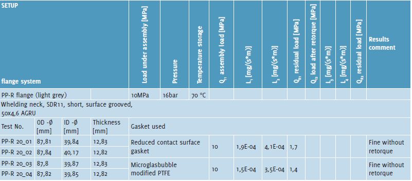
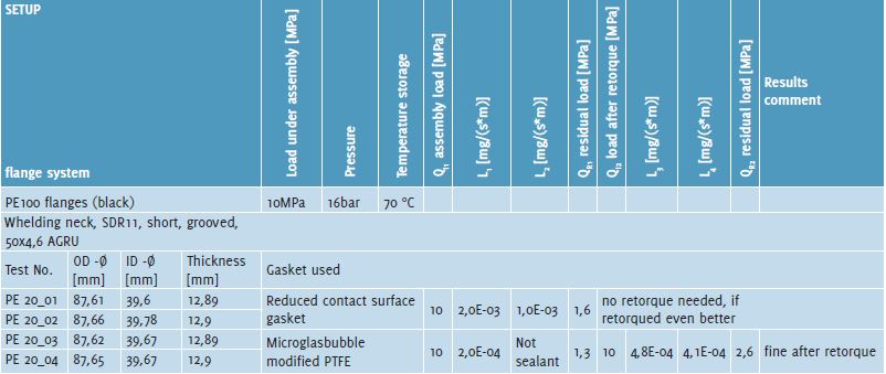
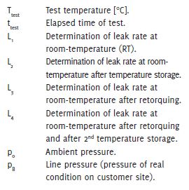
In accordance with abovementioned gasketing and flange materials, these have been tested with below shown results regarding PP-flanges. In accordance with abovementioned gasketing and flange materials, these have been tested with below shown results regarding PE-Flanges. In accordance with abovementioned gasketing and flange materials, these have been tested with below shown results regarding PVDF-Flanges.
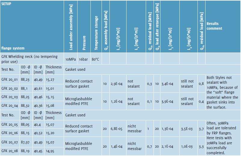
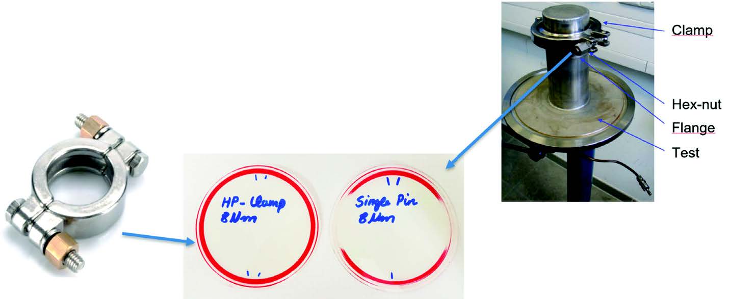
Also, in accordance with abovementioned gasketing and flange materials, these have been tested with below shown results regarding FRP-Flanges. Also, flanges in accordance with DIN 32676 (tri-clamp connectors), with the given disadvantage of an ‘non-normative clamp,’ can be tested in accordance with the new TA-Luft. Here, ‘tri-clamp gaskets’ were produced with modified PTFE materials. These modified PTFE materials will be included in the next revision of DIN32676. The results depend on the load created by the clamp which is loading the gasket. Any double screw clamp called ‘high-pressure clamp’ has had a very positive test result, because the load created on the gasket is more homogeneous. Figure 8 indicates the load with a pressure-sensitive Fuji film foil.
Using 8Nm torque to simulate a closing by hand, with a given line pressure of 16bar and temperatures up to 130°C, PTFE gaskets conforming to the DIN 32676 standard, providing reduced cold-flow – a gasket modified with aluminosilicate microspheres (micro-glass-bubbles), for instance – already could reach values of 4,9 x10⁻³ [mg/(s*m)]. Calanderized translucent multilayer pure PTFE gaskets, which also provide reduced cold flow and reduced creep by its production method, already could reach values of 2,4 x10⁻⁴ [mg/(s*m)]. The given normative value which should not be exceeded for this kind of test and connection is 1,0 x10⁻² [mg/(s*m)]. As a sidenote to the abovementioned gasketing technologies of PTFE to be used with tri clamp connectors: PTFE, since revision of DIN 32676 dated October 2022, is listed within the standard.
Conclusion
Plant owners will now have to do their homework. The previously used TA-Luft certificate, which was tested in normative steel flanges with given load using 1bar line pressure, cannot be used to fulfil the new German Air Quality Control TA-Luft regulation.
Now, commonly used gasketing materials on metallic flanges need to be calculated in accordance with EN 1591-1. The results will indicate the check of minimum load needed to be sealant and of maximum load not to be exceeded for the gasketing material, indication of reached sealability class, indication of used torque and check of all tensile forces, including screw/bolts and flanges, as well as rotation of flanges.
If no calculations are possible, the new test setup can be used successfully to prove the existing joint connection; even if ‘low-load’ flanges are given, modern gasketing materials can still be used to be in line with the new TA-Luft regulation.
References available on request.
About the author

Ralf Kulessa is a member of the ESA Flange Gasket Division. He has been working in the field of gasketing for more than 20 years, of which over ten years at Garlock. Prior to this, he worked for companies in the gasketing sector and for plant design companies, as well as within the prototype development of the automotive sector.
About this Featured Story
This Featured Story is an article from our Valve World Magazine, April 2023 issue. To read other featured stories and many more articles, subscribe to our print magazine. Available in both print and digital formats. DIGITAL MAGAZINE SUBSCRIPTIONS ARE NOW FREE.
“Every week we share a new Featured Story with our Valve World community. Join us and let’s share your Featured Story on Valve World online and in print.”


