
Check valves are used to prevent unwanted backflow in pipes and pipelines. Their design and operation may appear simple, yet proper care is required during selection to ensure that check valves function as expected.
By Masón Lu, Neway Valve

Check valves, also known as non-return valves, effectively prevent undesirable backflow without requiring external intervention. A common application for these valves is to stop backflow into a pump when it is shut down. A backflow may happen due to fluid pressure from the discharge side of a parallel pump (Figure 1). If not prevented, this reverse flow could potentially damage the pump.
When these valves are purchased as “bulk material” (for piping application), the process is often managed using a simple “material description” and without considering the VDS (Valve Date Sheet) process parameters, or installation conditions. Further, check valves may be subject to vibrations, shaking or hammering noises within the pipeline. These are all issues that Neway engineers have encountered in many instances.
Although check valves may seem to have a simple structure, there are still many factors to consider for installation and application. To help minimise any misunderstandings or errors, the below information is intended to help assist in the decision and selection process of check valves for specific applications. For precise application selection in specific conditions, additional input from FEA (Finite Element Analysis) is recommended. The following sections provide further details on commonly used check valves and application and selection recommendations.
Swing check valve
Swing check valves are a self-operating design which rely on the force generated by the backflow to close the valve. The disc of a swing check valve is like a mousetrap which allows a single direction for fluid to flow (Figure 2). This type of valve is not recommended for use in a vertical pipe when the flow direction is from upside to downside as gravity can tend to keep the valve open.
Swing check valves can also be modified with an external lever. This allows, for example, for external intervention as well as the fitting of hydraulic slow closing systems to reduce disc shock.
To deal with potential problems in application, Neway are focusing on developing special structures, including customisations with springs/lighter-obturators, or accessories such as dampeners, counterweights, etc.


Piston check valve
Piston check valves (Figure 3) are excellent selections for services where rapid flow reversal may occur. The travel is the shortest of all the check valves whilst the valve also has the fewest number of parts. The plug-type disc with spring loading has a better sealing performance in comparison with other types. However, piston-type check valves have a larger pressure loss due to the inflected body pattern. So, a Y type piston valve is an excellent replacement with better Cv than a T body pattern.
Dual plate check valve
Dual plate check valves (Figure 4) are widely used in the flow control industry for the following reasons: their better flow performance, compact installation space, lighter weight and no external leak risk due to the integral casting body. This valve is often installed with other types of check valve in series during the pipe layout. When installing a dual plate check valve, it is important to consider the operating space. For example, if the valve is close to an elbow or a pipe reducer, the disc may foul when opening and/or closing (Figure 5).


Tilting check valve
Tilting disc check valves feature quick-closing, low cracking pressure (Figure 6). A wide spectrum of applications includes pipelines containing high-temperature steam and hydrogenation. When systems require quick-closing valves, tilting check valves are often selected.
Axial check valve
Axial flow check valves (Figure 7) are a high-performance valve type, which are in compliance with API6D and ASME B16.34. They are widely applied in high-flow performance pipelines, not only to prevent medium flow back, but also to improve the pipeline flow performance. Axial check valves are also able to limit water hammer damage, are low noise and benefit from quick response times.
Check valve selection
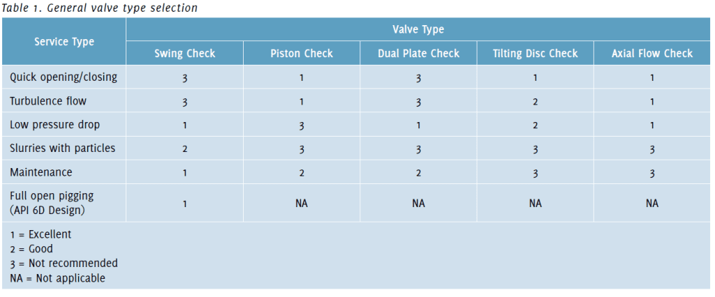
Table 1 below gives a brief comparison for these valves applied in different service requirements and working expectations. The information from Table 1, when combined with the check valve descriptions given above, can assist in identifying an appropriate valve selection.
In order to reach a specific flow data or more accurate disc status, FEA simulation will be necessary to give the user more accurate information. FEA may include service phase state, density, temperature, and inlet pressure/flowrate. The database should be clearly visible during selection to avoid confusion between Nm3/h (normal cubic metres per hour) and Sm3/h (standard cubic metres per hour). Nm3/hr and Sm3/h are both commonly used units of measurement to express gas flow rates and incorrect use can impact the calculation and FEA results.
Typical terms for check valve selection
When selecting check valves, it is important to consider flow control information provided by the valve manufacturer. For example:
- Flow coefficient Cv (or KV): If the Cv value of a valve is 1 this means the valve will pass 1 gallon per minute (GPM) of 60°F water with a pressure drop (Dp) of 1 PSI across the valve. Similarly, a valve with a Cv of 100 will pass 100 GPM of 60°F water with a pressure drop of 1 PSI.
- Equivalent length L/D: The pressure differential across the valve, equivalent to the length of a straight pipe that would produce the same pressure differential at the same flow rate. A smaller value indicates better performance.
- Flow resistance coefficient ζ (or resistance coefficient K): The head velocity loss caused by the valve is a concept in fluid mechanics. A smaller value indicates better performance.


Additional considerations during check valve selection
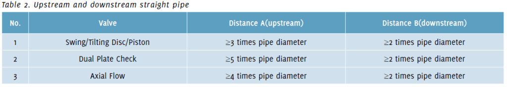
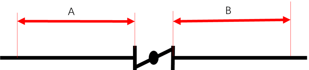
The diameter of the check valve should be compatible with the flow conditions to avoid mechanical damage caused by the continuous movement of the valve disc (opening and closing against the valve seat). If the flow is insufficient to keep the valve disc fully open, such damage may occur. This may be more concerning for larger check valves (greater than NPS 2) that have the same NPS as the pipeline. To minimise wear or damage to internal components, the check valve should also not be installed in areas with unstable flow, such as near changes in pipeline direction or close to pump discharges. In low-flow applications, it is advisable to consult design engineers for sizing guidance, as well as spacing recommendations in cases involving turbulence (both upstream and downstream refer to Table 2).
Vertical pipe installations may require additional considerations. It is advisable to avoid downward flow in API 594/API 602 type check valves unless an appropriately designed internal or external spring or counterweight is used to handle the required opening pressure. Dual-disc check valves are well-suited for installation in vertical pipes with upward flow, as both gravity and the internal spring aid in closing. Similarly, Y type check valves, as well as ball and lift check valves that rely on internal springs for closure, can also be used in vertical pipes with upward flow. Swing and tilting disc check valves can be used in vertical pipes with upward flow, but their closing response may be affected, as the closing force due to gravity is diminished when the valve is in the open position. (Figure 8).
Summary
Overall, there are many types of check valves to choose from. In addition to the valves described above, other types include single-disc check valves, foot valves, ball type check and axial control check valves. We want to emphasise the importance of not only calculating and analysing the on-site conditions when considering and selecting the appropriate valves for installation, but also the many factors that affect check valves that
need to be assessed during the selection process.
About the author
 Masón Lu is the Application & Technical Manager of Neway Valve (Suzhou). With nine years of technical experience, Lu has extensive field experience with valves in valve selection, maintenance and installation, including PDH, MMA, MDI and ABS. Lu has also authored and published the “Valve Application Technology Handbook”, contributing valuable insights to the field. This combination of practical knowledge and scholarly work positions him as a key asset in advancing valve technology and enhancing operational efficiency in chemical processing plants.
About this Technical Story
This Technical Story is an article from our Valve World Magazine, April 2025 issue. To read other featured stories and many more articles, subscribe to our print magazine. Available in both print and digital formats. DIGITAL MAGAZINE SUBSCRIPTIONS ARE NOW FREE.
“Every week we share a new Technical Story with our Valve World community. Join us and let’s share your Featured Story on Valve World online and in print.”