Article by ESA member Jan Kasprzyk
___
The distinctive material features of expanded graphite rings include:
- Low friction coefficient, estimated at a level of 0.1 for wet friction and 0.16 for dry friction
- Remarkable chemical resistance against most process fluids, including all fluids used in energy generation
- High resistance to nuclear radiation making them eminently suitable for applications in nuclear engineering
- Resistance to high temperatures exceeding the resistance of the most common sealing materials
- Relatively low cost
- High resistance to compression
- On the negative side, low resistance to tensile and shear forces
It is also significant that in terms of the applications where gland packings are used, our knowledge of this material and our experience is the most extensive. Initially in the seventies, the rings were made directly from expanded graphite particles by filling them into a tool or even by forming directly in the device (pump or valve). In this case, a problem occurred related to the low density of the expanded graphite particles and the high compression set. Because of this graphite foils with a higher density of 0.7 – 1 g/cm³ were used to form rings because they are easier to handle.
Apart from the various graphite foil qualities, the gland seals made from them are also distinctive in terms of varying structural forms and density. The density of the graphite rings as supplied is normally in the range from 1.3 to 1.8 g/cm³. Rings with a density of 1.8 g/cm³ can be used even in pressures exceeding 300 bar.
This density is a structural characteristic of the rings and with higher densities the pressure resistance is increased and higher contact pressures can be achieved. In terms of the structural forms of graphite rings, one may distinguish structures intended for valve stems or for static applications in self-sealing covers of fittings and valves and other static joints. In such cases the graphite rings can also contain metal components.
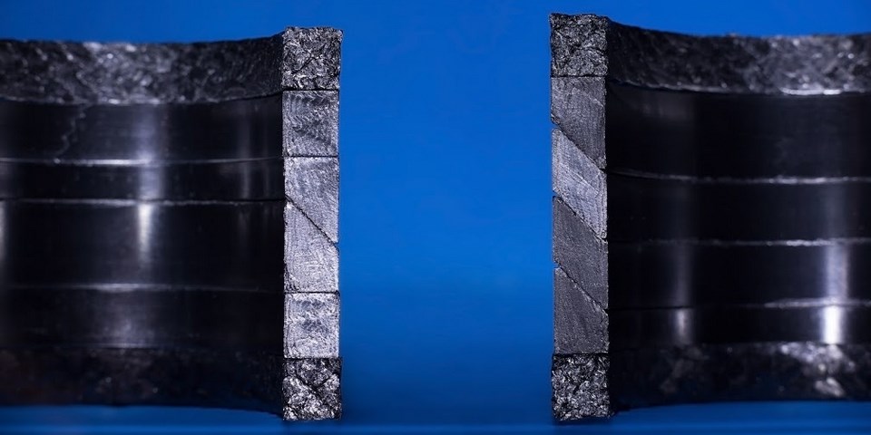
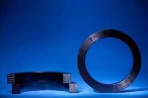
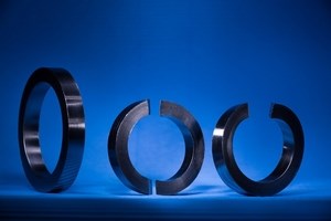
As mentioned earlier, graphite rings are made by means of die-forming graphite tape which is wound into a tool. As a result of this process, the lamellae inside the ring are arranged in a characteristic folded shape (Figure 1), which results in the fact that the axially applied pressure is efficiently converted into radial pressures with a pressure conversion coefficient (K) for these rings amounting to approximately 0.9. Seals for valves stems, when they do not contain metal components, may have an endless form, or a single or double cut diagonal to the ring’s axis (Figure 2). The cuts facilitate the installation of the ring during operation maintenance services, as they do not require the removal of the valve drive.
Expanded graphite, as mentioned at the beginning of this article, is characterized by very low breaking strength. In practice, this means that when axially compressed it may be extruded into the gaps between the gland and the stem, the gap at the bottom of the stuffing box and the gap between the gland and the wall of the stuffing box. As a result of this in high pressure applications and in the case of large diameters, where the gaps into which the graphite may be introduced are wider, special structural procedures are applied to minimize the extrusion.
One method used is to produce graphite rings that are laterally reinforced with metal foils – they constitute a type of laminate with flat, alternately arranged layers of graphite and metal foil. In this case, however, the transmission of axial stress into radial stress is only slight and such rings are therefore categorised as “antiextrusion rings” and not “sealing rings”.
Another method of reinforcement consists in die forming a metal-graphite laminate reeled on a mandrel. In this case, a form of two-component fold is formed in the crosssection of the ring (Figure 1). Its properties are also far from the basic structure’s properties. Here the rings are usually used as anti-extrusion rings as well, while they may perform a sealing function in case of high pressures. These rings are also used as spacer rings when filling the bottom space in long stuffing boxes. It is assumed that the maximum number of rings in a stuffing box is 6 – this results from the axial distribution of the contact pressures.
In static applications and sometimes in quasi-static applications, graphite rings used for high-pressure operation combined with large clearances (usually related to large diameters or high wear of the fittings and valves) are produced with steel jackets at the corners (Figure 3).
Such a jacket closes the gap and prevents the extrusion of the graphite. The jackets may be of various thicknesses between 0.5 and 1.5 mm and be made of different materials such as austenitic steel or nickel alloy. Such rings are most frequently used in self-sealing covers and medium and high-pressure fittings and valves. In this case, the cross-section of the ring may be square, rectangular or trapezoidal. A variety of other reinforcement methods are used such as the incorporation of a metal mesh, springs in the ring corners and geometrically complex combinations of follower rings and steel o-rings.
By combining different shapes, crosssections and/or densities of rings it may be possible to optimize the set in terms of its sealing integrity, lower the friction on the valve stem, minimize the wear or decrease the contact pressures. Some specific graphite set designs using these techniques are patented by sealing manufacturers.
The author is grateful to Jacek Faruga for provision of the figures.


