
This article discusses the essential equipment necessary to safeguard low-pressure storage tanks from pressure change events, addressing the challenges posed by new standards, narrow operating ranges and the need for precise system component coordination. It also provides valuable insights into effective tank protection strategies, focussing on operational safety and minimised environmental impact.
By Omar Cruz, Emerson
While storage tanks can safely store thousands of barrels of product, they are sensitive to overpressure or vacuum conditions, both of which can lead to product loss or excess emissions. Tank ruptures or implosions can result when the tank’s design limits are exceeded.
One straightforward solution is to install large vents on a tank, allowing it to release pressure or relieve the vacuum freely. This approach works well for tanks storing non-hazardous materials but poses significant safety and environmental risks for tanks containing volatile organic compounds. These tanks need a more sophisticated array
of protection devices to ensure product quality, operational safety and minimal environmental impact. Tank protection solutions might include a combination of tank blanketing regulators, pressure vacuum relief valves, gauge hatches, emergency vents and other equipment.
Meeting new emission requirements

There is a wide range of storage tank designs, but this article concentrates on low-pressure storage tanks holding liquids that are stable at room temperature. These tanks usually have a fixed roof construction that creates a vapour space between the stored liquid and the top of the tank. High-pressure and cryogenic tanks are beyond the scope of this article.
With these types of tanks, regulating the internal pressure within vacuum and pressure design limits is critical. Many storage tanks can sustain a vacuum of only a few inches of water, and the maximum pressure may be one PSI or less. Operation even slightly beyond design pressure or vacuum can result in immediate and catastrophic damage (Figure 1).
To avoid damage, the vapour space in the tank needs to be carefully regulated as ambient or operating conditions change. There are also a host of new regulation requirements released by the Environmental Protection Agency. Title 40 / Chapter I / Subchapter C / Part 60 / Subpart OOOOb/c (more commonly referred to as Quad O) mandates have been broadened to encompass storage tanks that commence construction, modification or reconstruction after 6th December 2022 and emit over six tons of volatile organic compounds annually. These tanks must reduce their emissions by a minimum of 95 percent.
Pressure control design
It may not be obvious, but tanks naturally and continuously breathe in and out due to various operating modes and environmental effects. To design a proper tank protection system, these effects must be fully understood.
Tanks tend to develop a vacuum and need to breathe in when the following events occur:
- Material is pumped out of the tank, so the volume of the liquid must be replaced with vapour.
- Ambient air temperature drops due to weather changes, causing the vapour in the tank to contract.
Tanks tend to develop excess pressure and needs to breathe out when these events occur:
- Material is pumped into the tank, so the volume of liquid increases, displacing the vapour space.
- A rise in ambient air temperature may result in the evaporation of the product into the vapour space, leading to an increase in vapour pressure.
- Fires in the area, for example a pool fire near the tank, will boil the contents and create an enormous vapour load that must be vented.
- Other overpressure scenarios depend on the tank contents and specific equipment around the tank.
Tank pressure control systems require a collection of equipment to maintain the tank pressure at a slightly positive level, often less than 10” WC. A typical tank pressure control system (Figure 2) usually includes a number of pressure control devices working together to provide layers of protection. Ideally, the tank pressure is maintained in the green zone by adding nitrogen through a blanketing regulator (Figure 2, Item 1) or by venting excess pressure to a scrubber/vapour recovery/flare system (Figure 2, Item 2). This arrangement keeps oxygen out of the tank, avoiding an explosive mixture in the vapour space, and it minimises vapour/product loss and environmental emissions.
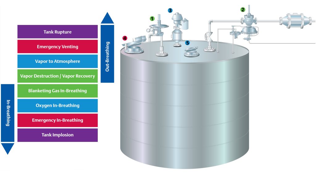
Unusual events, such as extreme weather, may overwhelm the capability of the first protection of layers and activate a tank pressure/vacuum vent into operation (Figure 2, Item 3). This vent pulls in air to break the vacuum, or it vents air to the atmosphere to relieve pressure. Regulations and codes require tanks to be protected with emergency vents to handle scenarios such as a nearby fire. In some cases, the tank pressure/vacuum vent (Figure 2, Item 3) can serve this purpose. However, many tanks will require a very large emergency vent (Figure 2, Item 4) to relieve the large vapour load created by this type of fire. Some tanks also include a thief hatch (Figure 2, Item 5) to allow manual level measurement and/or sampling of tank contents.
Pressure, vacuum and emission equipment design
Requirements will vary by tank and application, but a hazardous storage tank will usually require several different devices to provide pressure and/or vacuum relief. Each of these devices and their key selection criteria are discussed below:
Tank blanketing regulators
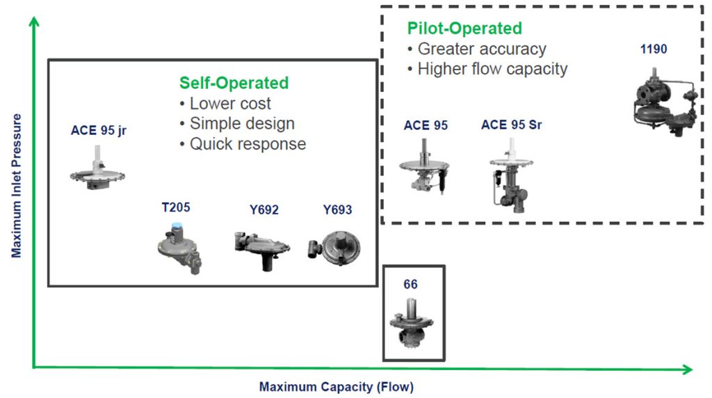
Tank blanketing regulators sense tank pressure and add an inert gas, usually nitrogen, to break the vacuum. As a good practice, tank blanketing regulators are set at a few inches of water, maintaining a slight positive pressure and keeping oxygen from entering the tank. Blanketing regulators face the challenge of accepting full-pressure nitrogen (often 80 PSI or higher) and reducing it to maintain a very low and tight tank pressure setpoint of one to two inches WC. There is a broad range of options for these regulators to cover various incoming inert gas pressures and flow capacities (Figure 3). Larger capacity regulators are often pilot-operated regulators with external pressure sensing tubes, and these are used for higher flows that elevate pressure at the regulator outlet. Blanketing regulators are specifically designed for this application, and key design features include very tight pressure control at low flow, and no leakage to the atmosphere during operation to reduce inert gas usage. High capacity or high inlet pressure will often require multistage, pilot-operated regulators.
Vapour recovery regulators
These back-pressure regulators vent tank vapours to a scrubber, vapour recovery system, or a flare so they can be processed in an environmentally acceptable manner. These devices typically provide control to a tank pressure setpoint of a few inches of water above the tank blanketing regulator, but a few inches below the tank vent set pressure.
Precise control with tight shut-off is required to avoid needlessly venting product vapours and/or nitrogen, and to prevent tank pressure from rising high enough to begin venting to the atmosphere through the tank pressure vent.
Key design features for this equipment include very precise control within a narrow range of extremely low pressures and exceedingly tight shutoff when not in operation. Regulator seals and soft goods must be carefully specified for compatibility with the tank vapours.
Note that downstream equipment and pressure conditions can impact the sizing and selection of this equipment. For example, a vapour recovery system may be operating at a vacuum, and its detonation arrestors can create significant pressure drops at higher flows.
Tank pressure/vacuum vents
Tank pressure/vacuum vents (Figure 4) should only come into operation during atypical conditions where the required flow rates exceed that of the blanketing and vapour recovery regulators. When these devices operate, they either intake air or vent tank vapours to the atmosphere. These blanketing and vapour recovery regulators are sized to avoid their operation in all but atypical conditions.
The key design features for this equipment are very reliable operation despite remaining inactive for months and even years, and near zero leakage when not in operation. Higher-tier products have leakage rates of less than 0.1 SCFH at 90% of the set point.


Conclusions
Sizing these devices and coordinating their operation takes knowledge and expertise. Design professionals who are unfamiliar with these processes and equipment specifications should consult with their tank pressure equipment vendor. This will help them better understand their options so they can select the right combination of devices for a particular application. A well-designed system will provide years of reliable service, while minimising nitrogen usage and environmental emissions, but a poorly designed system can place a tank and the surrounding environment at considerable risk.
About the author
 Omar Cruz has been working for Emerson for five years and is currently a marketing manager for Tank Products. He holds a BS in Mechanical Engineering, as well as dual master’s degrees in Innovation & Entrepreneurship and Business Administration, all from the University of Texas in Dallas.
About this Technical Story
This Technical Story is an article from our Valve World Magazine, March 2025 issue. To read other featured stories and many more articles, subscribe to our print magazine. Available in both print and digital formats. DIGITAL MAGAZINE SUBSCRIPTIONS ARE NOW FREE.
“Every week we share a new Technical Story with our Valve World community. Join us and let’s share your Featured Story on Valve World online and in print.”