These seals, together with the seat will make or break the tightness requirements (1.5 ml/min/mm bore, He @ -196°C). Spring energized PTFE seals (commonly called Lip seals) are used for this task in a variety of geometries, materials and sizes. At temperatures down to –75°C, and possibly even lower, these standard designs may be able to comply with current tightness requirements. At lower temperatures this task becomes increasingly difficult if not impossible. The novel Single Piston Effect seal described and explained below may well be able to remedy all the root causes which contribute to the tightness problems seen with current designs.
Factors impacting seal performance
- Seal design and materials
- Groove design and finish
- Inter action valve –seal
- Valve mechanics
- Pressure
- Medium
Seal Performance Factors
All the mentioned factors have to be thoroughly investigated and taken into account when sealing LNG. There is not a single most important factor that dictates success or failure.
For any seal to obtain the best possible tightness there is a need for intimate contact between the seal and the mating surfaces. At higher temperatures the lipseal material flows relatively easy, thereby mirroring the mating surfaces and creating a good seal, this is not a given anymore at cryogenic temperatures.
At room temperature and above, the available seating load, generated by the spring compression and increased by the system pressure is typically enough to create intimate contact between seal lips and mating surfaces.
How much seating stress is needed?
Surface finish, the medium and the required tightness determine the required seating stress. For gas tightness and with good surface finish the seating stress should approach the yield stress point of the jacket material. At room temperature this is about 5 MPa.
A standard helical lip seal spring will generate approximately a load of 5 N/mm circumference. Depending on the lip shape this unit load means an average seating stress of not more than 5 MPa. Every 10 bar pressure increases the seating stress with only1 MPa.
Many applications prove that lip seals operate satisfactory at room and higher temperatures. Given acceptable surface finish on the seal and the mating surfaces, bubble tight seal performance can be achieved.
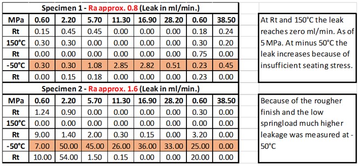
The following test results where a well-polished seal and a seal with rough surface have been tested show clearly the impact of seating stress. The spring in both cases was a low load V spring. The surface finish of the groove was Ra= 0,4

What makes it than so difficult to perform well at cryogenic temperatures?
While cooling down, the polymers, used as jacket material, would shrink by a factor 10 times higher than the surrounding groove material and in addition the seal material becomes increasingly harder. These two factors contribute in not a small amount to the difficulties seen at cryogenic sealing.
At liquid nitrogen (LN2) temperature the yield strength and the E-modulus of typical PTFE or PTFE compounds increases 10-fold, the hardness as a consequence, increase also by a factor 10. In addition, if the spring would not stop it, the outer seal lip would shrink approximately 2%.
These radical changes work negative on the seal performance.
The shrinkage force of the outer lip works opposite to the original spring force, reducing the seating stress and sealing capability of the outer lip. Contrary the inner lip seating stress increases because of the shrinkage force.
The shrinkage because of cryogenic temperatures creates a second issue. Since it is impossible to manufacture a helical spring with a “0” gap at the outer diameter, the shrinking polymer will shrink into these gaps and reduce over a short distance the seating stress. One can try to reduce this gap as far as possible by manufacturing a “0” gap coil. However once assembled in the seal cavity a small or bigger gap will be formed. An attempt to remedy this problem by using an overlapped spring may well do more harm than solve the problem. At the overlap, a small triangle shaped void is created. This allows the polymer to shrink minimally more at this location, so that a kind of wave form load distribution is formed.
Where at room temperature and higher temperatures a relatively low spring load (1 to 5 N/mm circumference suffice, this not the case anymore at lower and cryogenic temperatures.
The increased hardness of the polymer jacket requires a far higher spring load compared to higher temperatures. At LN2 temperature the hardness of commonly used polymers comes close to the hardness of copper at room temperature. With this kind of hardness the spring will be far too weak to plastically deform the Polymer jacket. And there is not much to do about it. A strong(er) spring will eventually counteract the shrinkage of the outer seal lip in a better way than a weak spring but it will fail to come anywhere close to the yield strength of the polymer jacket at LN2 or LNG temperature. It needs to be said that a stronger spring also yields a lower elasticity. Also the available groove size, limits the increase in spring load and flexibility. In addition a stronger spring also hinders the movements of the dynamic seat ring. Secondly a high spring load would embed partially in the seal lip, thereby reducing much needed elasticity and also its actual load.
Valve mechanics, tolerances in general and external loads, work mostly negative on seal performance.
Given a perfect designed seal, with a high load spring with zero gap coil, highest flexibility and with polished surface, assembled perfectly in a clean and polished groove. What, in such case, impact the performance of a radial seal in a negative way?
To reach the maximum performance under the bespoke conditions, the spring needs be compressed equally over the complete circumference. This means that the valve body and the dynamic seat rings needs to be perfectly cylindrical and in assembled condition there shall be no eccentricity between the two parts. Only when this is the case, the radial groove size will be uniform over the complete circumference, and so will be the seating load.
It shall be clear that any deviation from the above results in un-equal compression of the spring and as such also in a non-uniform load distribution over the circumference of the seal.
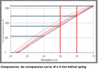
In operation, the above perfect situation from a sealing point of view may be downgraded because of deformations, caused by the cryogenic temperature, system pressures and line loads. These deformations might be small in absolute figures, but from a seal point of view they can be gigantic. As an example, a 1/4 inch radial seal has a spring cross section of 5 mm. Assuming 20% spring compression gives 100% compression load, than 0.2 mm compression reduction equals a load reduction of 23% and a loss of compression of 0.4 mm would equal a load loss of 43% of the original load. These figures are valid for a high quality spring. The results with lower quality springs (high hysteresis) would be worse of course.
Polymer shrinkage reduces the outer seal lip load.
Polymer shrinks into spring gaps, locally reduces the load.
The increased hardness of the polymer at cryogenic temperatures poses a formidable challenge.
Valve size tolerances and or deformation will impact uniform load.
In conclusion, a radial seal as a SPE is critical regarding tightness because of shrinkage of the Polymer itself, the differential shrinkage of the Polymer and the valve material, the valve mechanics and last but not least the increased hardness of the Polymer material.
Standard Single Piston Effect Seal
There is a way to go around the difficulties encountered in the classical radial seal design. The major problem in the existing radial seal is the outer lip. Differential shrinkage, hardness increase and therefor lack of sufficient and uniform seating load create tightness problems at the outer lip.
When the valve reaches an equal temperature the seating load at the OD lip will not significantly increase.
With this shortcomings a highly polished inner and outer seal groove finish is a primary requirement. The spring should have a high enough load to counteract the shrinkage force of the seal and seal lip. But the spring load is also limited to a certain level to avoid too much cold flow at higher temperatures and to avoid a too high friction versus the dynamic seat.
By splitting up the sealing task of the seal into a radial part, sealing the dynamic seat, and an integrated face seal, sealing the body, many, if not all of the bespoke problems with the classical radial seal solution can be resolved.
Novel Single Piston Seal (Patent pending)
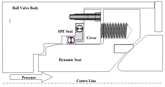
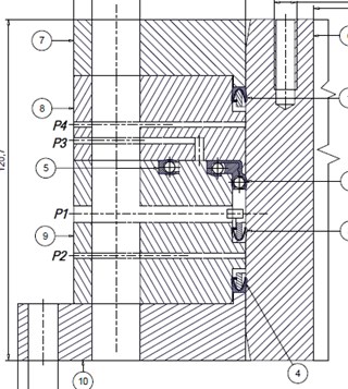
In the below sketch a possible example of such an integrated radial-axial seal is given. The seal jacket may be machined as one integrated seal or an interlocking radial and face seal. The cover holding the seal, locked in place, in the valve body needs to be sufficient rigid to counteract the system pressure.
Pro:
The load on the outer radial lip is irrelevant. This lip has no sealing function.
The load on the inner lip can be engineered for minimal drag forces on the dynamic seat, allowing the seat push springs to deliver the maximum load to the seat. The sealing towards the body is solved by the face seal part of the integrated seal.
The spring load of the face seal can be as high as possible to allow maximum sealing performance.
Eccentricity of the dynamic seat versus the body is less critical.
No need for difficult machining/polishing of the outer diameter.
The test fixture as shown above, is set up in such a way that the standard seal and the special patent pending radial-axial design is tested under exactly the same conditions.
The pressure is applied to both seals via port P1. Port 3 allows the leakage measurement over the outer diameter of the seal, whereas port 4 allows the leakage measurement over the seals inner diameter. Via port 3 the leakage over the standard radial seal is measured.
A temperature sensor (not shown in the above sketch) is located 1 mm away from the radial outer diameter of the novel seal design.
To cool down, the test fixture it was placed in cool box. The temperature of -100°C and -170°C was created solely by evaporation of LN2. In order to reach -196°C the test fixture was submerged in LN2. Enough time was let to assure an equal temperature over the complete test fixture.
Seal ID 228 mm, Cross section 3/16”
Test medium in all cases: GHe
Prior to cryogenic testing a Helium sniffing test was carried out.
This table reflects the results with a standard shaped novel SPE seal and slightly improved version of a standard SPE seal.
In total 3 different sets of seals were tested. Without an exception the novel SPE design showed the lowest leak rates.
One of the standard seals was a 3/16 inch helicoil spring energised seal, the other a V spring energised seal.
These two standard seals at -196° and 100 bar showed a leakage exceeding 1000 ml/min. (max capacity of flowmeter).
1) The novel SPE seal design offers potential to zero leakage at normal LNG operation conditions.
2) The design requires an additional part for the valve.
3) The extra cost related to this design can be offset by;
a. easier and less costly finishing cost at the bore location
b. first time success with FAT
4) Better finish at seal level and valve level will yield better seal performance
5) Seal design, careful handling and assembly are key to success.
6) A clean and dust free assembly environment would be good.
Francis Lebeau is a product specialist in seals for extreme service conditions, currently consulting for Fluorten, a world class company designing and producing high performance polymer products. He has been active in this market for the last 30 + years, specializing in the design of high performance spring energised PTFE Seal and Resilient Metal seal solutions. He holds 3 patents relative to seal applications. Francis has also been involved in the
design and selection of the majority of the Polymer and Metal seals in use on the main cryogenic engine and valves of the Ariane 5 rocket.