
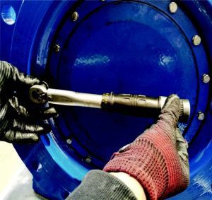
Butterfly valves are widely used in water systems and industrial pipelines, where maintaining a tight seal is essential for preventing leaks and ensuring reliable operation. This technical article investigates how bolt tightening torque affects the sealing performance of rubber seals in butterfly valves.
By Ahmed Obaid, Sierra
Butterfly valves are commonly used in water networks, process plants and industrial systems due to their simple design and efficient flow control. One of the key components in ensuring proper sealing is the rubber seal on the valve disc, which forms a seal by compressing around the valve disc when closed.
 However, the amount of tightening torque applied to compress the rubber seal plays a critical role in performance. If the torque is too low, the rubber does not compress enough, leading to leakage. If the torque is too high, the rubber gets over-compressed, which causes early deformation, loss of elasticity, higher valve operating torque and reduced lifetime. This article outlines a mathematical approach used to estimate the optimal tightening torque to ensure sealing without compromising the integrity of the rubber seat. A practical test is also discussed to validate the method.
The following figures illustrate the effect of bolt tightening torque on the compression of the rubber seal. As shown in Figure 2, excessive or uncontrolled torque can deform the seal due to elevated contact stress. This leads to greater radial expansion of the rubber, which in turn increases the pressure stress caused by contact with the valve seat. Consequently, the friction force acting on the seal during opening and closing is increased, raising the likelihood of accelerated wear.


Minimum required rubber seal diametral expansion
To achieve an effective seal, the rubber seat must expand slightly outward (radially) when compressed by the disc. This expansion generates a contact pressure that pushes against the disc surface, strong enough to resist the internal pressure of the fluid flowing through the pipeline.
The required amount of expansion depends on:
- The amount of tightening torque of retainer bolts which compress the seal rubber
- Number of retainer bolts
- Retainer bolt size
- Contact area between retainer and rubber seal
- The stiffness (hardness) of the rubber material
- Rubber seal thickness
This radial expansion must be carefully estimated to provide enough sealing pressure, while also including a safety margin to account for manufacturing tolerances, aging and thermal effects.
FP = Pressure force (N)
Fn = Normal force (N/mm)
Ft = Friction force between rubber seal and seat (N)
To ensure no leakage, the friction force must be greater than pressure force acting on the disc seal.
Equation 1
Ft ≥ Fp
Ft = μ * π * Dseal * Fn
μ – Coefficient of friction between rubber and valve seat
Dseal = Rubber seal outer diameter
The normal force due to compression between rubber seal and seat can be explained according to the following equation:
Equation 2
Fn = 2 * Pmax * r * sinθ
Pmax – Acting pressure between seat surface and rubber
R – rubber radius
Θ – Shown in Figure 3
Equation 3
![]()
ΔL – rubber seal radial expansion
E – young’s modulus of rubber
Equation 4
![]()
b – Shown in Figure 3
By substituting equation 4 & 3 in 2:
Equation 5
![]()
Equation 6
Fp = p * Aprojected
P – Water pressure
Aprojected – Seal projected Area to acting water pressure [Aprojected = π * t * DSeal]
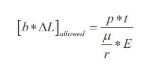
By substituting equation 5 & 6 in 1:
Equation 7
![]()
 Equation 7 illustrates the amount of sealing rubber engaged with seat.• The term b*ΔL can be found by using CAD software by drawing the engaged rubber seal with valve seat and measuring the values of b & ΔL in the drawing.
- So, to ensure effective sealing performance [b*ΔL]CAD ≥ [b*ΔL] allowed.
- After determination of the values of b & ΔL, the tightening torque must be calculated to achieve these values and achieve the optimal sealing.
 Equation 7 illustrates the amount of sealing rubber engaged with seat.• The term b*ΔL can be found by using CAD software by drawing the engaged rubber seal with valve seat and measuring the values of b & ΔL in the drawing.

Rubber seal bolts tightening torque
Once the target expansion of the rubber is known, we need to determine how much axial force is required to produce this deformation. This force is what actually compresses the rubber between the valve body and the disc. The tightening torque applied through bolts must be enough to generate that compression force.
The required torque depends on:
- The size of the bolts
- The friction between threads and under bolt heads
- The friction between bolt head and retainer
- Number of retainer bolts
- Seal thickness
- Seal stiffness
- Contact area between rubber seal and retainer

Care must be taken to not exceed the torque limit. Exceeding this value can permanently deform the rubber or even damage the seat during assembly or operation. Using lubricated bolts or anti-seize compounds may also influence the torque required, since frictional resistance is reduced.
From equation 4, we can calculate the value of sealing rubber deflection (ΔL) due to bolts tightening.
So, lateral strain can be calculated in the following equation:
![]() L – Rubber seal profile length before deformation (shown in Figure 5).
L – Rubber seal profile length before deformation (shown in Figure 5).
Poisson ratio created a relation between lateral deflection and longitudinal deflection:
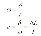 ω – Poisson ratio
δ – Lateral strain
ε – Longitudinal strain
Equation 8:
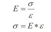
σ – Compression stress effected by retainer on the rubber seal (N/mm2)
E – Young’s modulus (N/mm2)
The retainer maintains a fixed force acting on the rubber seal to fix the rubber on the valve disc:
Equation 9
![]()
Fretainer – Normal force due to bolt tightening (N)
Acontact – Contact area between retainer and rubber seal (mm2)
From equations 8 & 9:
Therefore, acting force per bolt can be calculated by the following equation:
![]() Fa – Preload acting per bolt to achieve tightening between retainer and rubber seal (N).
Fa – Preload acting per bolt to achieve tightening between retainer and rubber seal (N).
Now, tightening torque per bolt can be calculated as following:
Equation 10
T = T1 + T2
T – Total tightening torque (N.mm)
T1 – Friction torque between bolt and threads (N.mm)
T2 – Friction torque between bolt head and retainer (N.mm)
Equation 11
![]()
rm1 – Bolt mean radius (mm)
μ’ – Inclined friction coefficient between threads
![]() β- Inclination angle of threads = 30°,
β- Inclination angle of threads = 30°,
μ2 – friction coefficient between threads.
![]() α – Helix angle of threads
α – Helix angle of threads
Pi – Bolt thread pitch
dm – Mean diameter = ![]()
do – Thread outer diameter
di – Thread inner diameter
rm2 – Bolt head mean radius
μ3 – Friction coefficient between bolt head and retainer.
Summary
This study presents a practical approach to determining the optimal tightening torque for butterfly valve rubber seals. The goal was to ensure a reliable seal without over-compressing the rubber, which can lead to premature wear and failure. By analysing the required expansion of the rubber seal to generate sufficient contact pressure, and translating that into the corresponding compression force and tightening torque, a safe torque range was established.

References
Al-Ghathian, 1Faisal M. M. and 2Tarawneh, Muafag S. (2005). “Friction Forces in O-ring Sealing.” American Journal of Applied Sciences, 2 (3).
Werencke, W.P., (1987). “Analysis of the reciprocating sealing process”. 11th Intl. Conf. On Fluid Sealing. Cannes, France.
Johannesson, H. and E. Kassfeldt, (1989). “Calculation of pressure distribution in an arbitrary elastomeric seal contact”. Wear, 130: 3-15.
About the author

Ahmed Obaid is a Mechanical Design Engineer at Sierra for Engineering and Manufacturing, an innovative valve manufacturing company where he applies his studies. With extensive experience in valve and gearbox design, casting and manufacturing, he specialises in designing high-performance butterfly valves, check valves and plug valves according to AWWA and EN standards. His achievements include conducting advanced studies on sealing rubber behaviour to enhance product durability.
About this Technical Story
This Technical Story is an article from our Valve World Magazine, May 2025 issue. To read other featured stories and many more articles, subscribe to our print magazine. Available in both print and digital formats. DIGITAL MAGAZINE SUBSCRIPTIONS ARE NOW FREE.
“Every week we share a new Technical Story with our Valve World community. Join us and let’s share your Featured Story on Valve World online and in print.”