^ Fig. 1. The stacking of PAU-B over PAU-A.
Article by Rajeev Rai, Fluor India Pvt. Ltd., India
___
Module design
In 3rd generation modularization, the modules are designed to maximum height so as to house the larger equipment, accommodate process requirements, and provide adequate areas for maintenance activities. Whereas in stick-built projects the plant layout is developed to maximize the use of width and minimize the height of technological structure requirements.
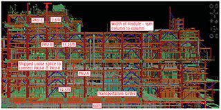
The module design has a structural floor-based soffit above grade. The soffit is designed to maintain the module’s structural rigidity and to facilitate handling and transportation. Vertical breaks and horizontal breaks of pre-assembled units are necessary to achieve the required module heights necessary to accommodate larger equipment, meet process requirements, and provide adequate space for maintenance. For ease of shipping, transportation, and for weight limitation, modules can be split horizontally into two or three PAUs and finally assembled at the installation location or the staging area. The dimensional sizes and weights of the pre-assembled units (PAUs) are defined by shipping and transportation constraints, like available barge capacity, clearance requirements, and road design. Stick built design should be used where larger equipment may be required, such as tank farm areas and tall distillation columns where the advantages of modularization are limited. Fig. 1 shows the stacking of PAU-B over PAU-A.
Equipment arrangement in modularization
The layout of equipment should be organized such that equipment from the same system are grouped together in a module to ensure the piping meets the process requirements. Large rotating equipment and heavy equipment should be located at floor level of the module to maintain a lower center of gravity for transportation purposes. The equipment should be spaced in a module as per the minimum spacing requirement of the local regulatory norms. Proper interdisciplinary coordination and coordination with the weight management team is required to finalize the locations of the equipment so that the center of gravity and the weight of the module is within permissible limit. Vertical stacking of equipment in lieu of horizontal spread can be considered as this approach allows the module to be built as a complete unit for pre-commissioning at the fabrication yard prior to shipping.
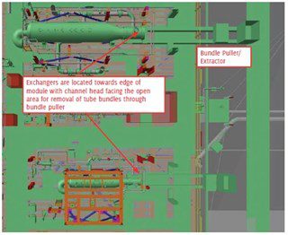
A proper mechanical handling study needs to be carried out for removing the equipment, internal parts, valves etc. and this should be based on their weight and size. This can be done by issuing drawings to the client on which the mechanical handling equipment to be used is clearly marked. This is important as the modules are compact and there is limited access for the items to be removed for maintenance. Fig. 2 shows a module with three PAUs (A, B, and C) stacked one over the other after installation.
Vessels in module
Horizontal and vertical vessels should be located such that they are housed in a single PAU without needing to split the vessel. Vertical vessels having a height exceeding the PAU shipping limit should be shipped separately and reinstalled at the staging area or at site. Vertical vessels can be designed in the module without skirts and can be supported within the module structures.
Vessels having very large diameters or width (length) like flare knock out drums, slug catcher drums, and large condensate drums should be made part of the stick-built design as the required modularization benefit cannot be achieved by including them. Nozzle orientations and support requirements for the vessel like (ladders and platforms, and vessel clips, etc.) should be provided well in advance as the vessel will be first transported to the module fabrication shop for installation in the PAU.
In the case of a modularized project, the delivery of equipment is much earlier when compared to a stick-built project. Late input to the vendor will lead to delays in the delivery of equipment to the module yard and will have an impact on the fabrication schedule, transportation, and installation of the finished module at site. To eliminate this, all the engineering input from upstream disciplines should be worked out and be provided as per schedule in a sequential manner.
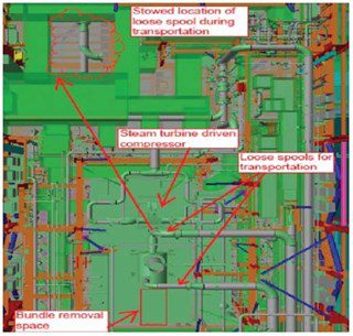
Compressor in the module
As the compressor is a piece of equipment that vibrates, it should be located on the lower level of the module. This will help to avoid increased vibrations and minimize structural requirements. Further, the lube oil console and its system should also be located within the module. A mechanical handling study should be carried out and the facility should be provided with a proper laydown area adjacent to the compressor for maintenance work and removal.
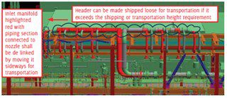
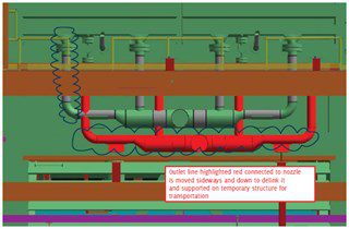
The inlet and outlet lines connected to the compressor should be shipped loose during transportation as the compressor is a strain-sensitive piece of equipment. The transportation of loose spools should be so arranged that they are stowed at the designated location and properly supported during transportation. For a reciprocating compressor the line routing with supports should be provided to the vendor at the earliest to take care of supports required as a result of the pulsation study. As such, proper coordination and tracking of data is required between the vendor and engineering team to avoid delays. See further Fig. 8.
Piping considerations at interfaces
The piping design should be so arranged as to minimize the number of interfaces so that the eventually reduced work at site will have improved safety. Welding requirements at the interfaces that need to be carried out at the site between PAU to PAU and PAU to PAR can be reduced by providing flanged interfaces for non-hazardous services (150# services). Loose spools are required at the interfaces as opposed to single weld hookups to ensure that the module height constraints during shipment are not exceeded, and that proper clearances in the soffits are maintained during transportation. These loose spools are also required where the shipping envelope is exceeded.
The following points should be considered while designing loose spools:
- The spool should have a minimum size and weight for improved rigging and reinstatement. They should have simple configurations.
- All the loose spools that exit a module on a common elevation should be grouped together and supported on a common frame for transportation and the lines can be lifted in a single crane lift.
- The use of C-shaped spools located outside of the module edge can be used for improved crane access for reinstatement and for lines routed vertically from PAU-A to PAU-C to minimize the number of interfaces. See further Fig. 10.
- Spools should be designed to minimize scaffolding requirements and interface welding should be planned such that the weld is 1000–1400 mm above the platform.
Figs. 9 and 10 shows some typical loose spool configurations. The closed drain lines from various sources of equipment and the lines in the module are connected to form a common sub-header and are run under the lowest deck to connect to the main closed drain header. The sub-header running under the lower deck flows under gravity and is located and routed outside the soffit beam for improved construction access during installation of the piping.
This minimizes the need for large support frames attached to the underside of the module. In the case of multiple lines, the lines running under the soffit are supported on structural frames, with larger lines running outside the soffit beam. All these lines will be stick built. To minimize site work, the drain lines should be located deep in the soffit where possible and made part of the modular design. This requires conformation with the structures providing beam penetration.
Conclusion
Modularization is gaining in importance in today’s world and for the future where the main focus is on safety, quality and scheduling. Because of this it is certainly becoming imperative to understand and develop expertise in layout development in a modular project environment.
About the Author

Rajeev Rai is a graduate in Mechanical Engineering working as a Piping Engineer with Fluor Daniel India Pvt. Ltd. He has more than fourteen years of experience in refineries and petrochemical projects in FEED, Detail Engineering, and Field Engineering at sites and within modular projects.