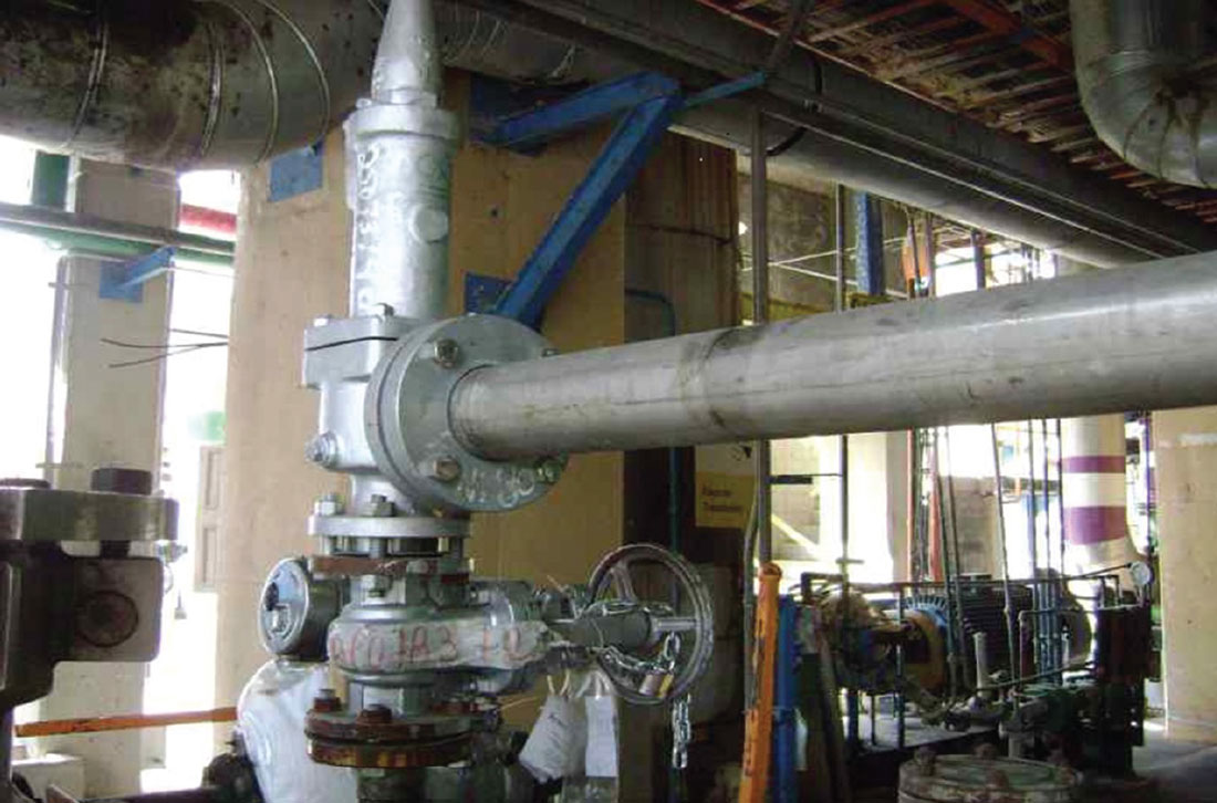
The installation of safety and relief valves in pressure vessels and the use of stop valves upstream and downstream are considered the last lines of defence for equipment subjected to an internal pressure greater than atmospheric pressure. However, this protection can only be guaranteed through periodic maintenance.
By Arthur Mathias
Pressure relief valves (PRVs) are ap-plied in various industrial segments such as oil refineries, pulp and paper, fertilizers, chemical and food industries etc. These valves are applied to protect pressure vessels constructed per ASME Code Section VIII – Division 1. In this way, the protection of lives, the environment, and invested capital occurs through correctly dimensioned, specified, installed and subsequently inspected and maintained PRVs.
Depending on the industry, the user may need to periodically remove these valves for inspection and maintenance. It may be necessary for the plant to be completely shut down before this maintenance can be carried out.
When the user foresees this need, at least two PRVs must be installed, with the individual flow capacity of each valve being responsible for at least 100% of the capacity required by the process. Thus, one safety relief valve will always be exposed to the process, while the other safety relief valve will be in reserve. In such an application, both valves must have their set pressures limited to the same value of the MAWP (Maximum Allowable Working Pressure). With this arrangement, the user can always remove one safety relief valve for maintenance while the process continues to operate and is protected by the other safety relief valve.
ASME Code Section VIII – Division 1 (Edition 2021), in its Appendix M, only allows the use of upstream and downstream PRV stop valves for the purpose of removing them for maintenance.
Gate or ball valves recommended
Both ASME Code Section VIII – Division 1 and API Std. 520 Part II (Installation) recommend the installation of full-bore shut-off valves, i.e. gate or ball valves. Both types provide minimal pressure drop when fully open. These valves must be locked with a chain and padlock in the 100% open position. These valves must under no circumstances be able to operate in partially opened positions.
Some users are unaware of the constructive design of valves applied for blocking, and thus end up using globe-type valves for blocking safety and relief valves. However, globe valves provide a high-pressure drop (high energy loss) even when they are 100% open due to their internal geometry. In these valves, the flow changes direction twice by 90°, while in a gate or ball valve, the flow passage is completely uninterrupted.
To make a comparison between the pressure drop provided by a 2″ size gate valve or ball valve and a 2″ globe valve: in the gate valve and ball valve the pressure drop is equivalent to a straight pipe of 0.7 meters pipe, while in the globe valve the pressure drop caused is equivalent to a 17.68 meters straight section of pipe. This high-pressure drop provided by globe-type valves results in a three to four times lower flow capacity than in a gate or ball valve. For example, still using the example of the valves above, while a 2″ diameter gate valve has a flow coefficient (CV) of 309, a straight-type globe valve has a flow coefficient of only 47. The region between the outlet nozzle of the vessel and the inlet connection of the safety and relief valve must provide the lowest possible pressure drop so as not to influence the operating performance of the valve.

Maximum pressure drop
ASME Code Section VIII – Division 1 and API Std 520 Part II recommend that the maximum pressure drop between the vessel outlet and the safety relief valve inlet connection does not exceed 3% of the set pressure at its carrying capacity rated flow. A greater pressure drop can cause an operational phenomenon called chattering. This phenomenon provides cycles of rapid opening and closing of the disc against the valve nozzle (and against the flow direction). Chattering occurs at the set pressure, preventing pressure relief by the valve and, consequently, increasing the pressure inside the vessel.
This phenomenon occurs due to high-pressure drop in the inlet pipe caused by incorrect specification of the stop valve (when applied). The inside diameter of the inlet pipe is smaller than the inside diameter of the inlet connection of the safety and relief valve. Safety relief valve oversizing is another likely cause for chattering when the flow rate delivered by the process is less than 30% of the safety relief valve’s rated flow capacity.
Either installing a high-pressure drop (low-pressure recovery) stop valve in the inlet piping or an undersized inlet piping, or an oversized safety relief valve, results in a reduction in the forces acting under the disc holder and inside the huddling chamber which holds the valve open during pressure relief.
The pressure drop that occurs in the pipe section between the vessel outlet and the valve inlet is directly proportional to its length and peak flow velocity and inversely proportional to its internal diameter. For this reason, it is always recommended that the internal diameter of the inlet pipe is equal to or greater than the diameter of the inlet connection of the safety and relief valve, and never smaller than the internal diameter of the nozzle throat.
Final conclusions
PRVs are considered the last line of defence for equipment subjected to an internal pressure greater than atmospheric pressure. However, this protection can only be guaranteed if the safety and relief valves undergo periodic maintenance. Reliability in the correct operation of a safety and relief valve cannot depend on the quality of its design if it is not correctly dimensioned, specified, installed, inspected and maintained. The use of upstream and downstream stop valves allows their removal for maintenance and inspection.
 About the author
Arthur Mathias is an industrial mechanical and chemical technician and a Member of ISA. Now a consultant, he has been active since 1985 in the maintenance, inspection, specification and sizing of valves. Arthur provides training and technical courses, and is the author of Válvulas: Industriais, Segurança e Controle published by ARTLIBER EDITORA.
About this Featured Story
This Featured Story is an article from our Valve World Magazine October 2022 issue. To read other featured stories and many more articles, subscribe to our print magazine. Available in both print and digital formats. DIGITAL MAGAZINE SUBSCRIPTIONS ARE NOW FREE.
“Every week we share a new Featured Story with our Valve World community. Join us and let’s share your Featured Story on Valve World online and in print.”


