

The ultimate mission of the pipeline operator is to transport hydrocarbons with the highest standards of safety, reliability, efficiency and environmental responsibility. This mission cannot be achieved without assuring valve integrity
Mousa R. Al-Harbi, Engineering Consultant, and Bader M. Jarallah, Valve Engineering Consultant, Saudi Aramco
Failure of a valve in a hydrocarbon network may cause a reduction in availability and reliability of the entire system, and also lead to the creation of potential conditions for major accidents in the form of hydrocarbon releases, fire and/or explosions. As such, valve integrity management should be a key aspect of each Pipeline Operator’s overall integrity management requirements. A risk-based approach is recommended to ensure effectiveness and optimise the expenditure. The paper provides a general guideline for the development of maintenance management system for pipeline valves.
Risk-based approach
The traditional approach adopted by operators to assess valve integrity is called a fixed approach where all valves are inspected and maintained on a fixed interval (identical scope at fixed intervals). This approach is simple to implement and manage. However, considering the large number of valves in pipeline networks, assessing valve integrity could be a tedious, lengthy and costly process.
Riskbased approach would be a better proposal as it prioritises the maintenance of assets that carry the most risk if they were to fail. This approach allows operators to determine the most economical use of limited maintenance resources to minimise the total risk of failure across a facility. To achieve an effective valve integrity management programme, a structured and systematic process should be followed considering two factors: criticality analysis and risk assessment.
1. Identification of failure modes
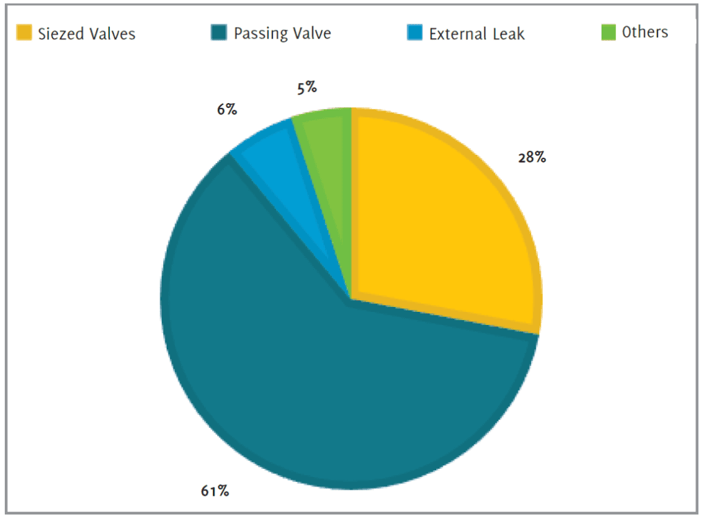
The first step of effective integrity management is to define the potential failure modes. This is essential to manage the risk through the establishment of the necessary measures to inspect, monitor and maintain the valves. The typical failure mode distribution in upstream facilities is shown in Figure 2. Failure mode is defined as the manner or data in which a system, structure or component fails.
Using this definition, the valve failure modes were classified according to four categories:
- External leak: defined as loss of the ability to contain pressure. Basically, this refers to the release of product to the environment through the valve body, valve body joints, valve packing, or through the valve auxiliary piping and accessories.
- Seized valve: defined as the failure to operate or a valve facing difficulties operating when required (shift from open to close position or vice versa).
- Passing valve: refers to excessive leakage from the valve where the valve fails to achieve the required isolation level.
- Others: Other reported failures that may affect the valve performance, such as external corrosion, blockage of the injection fittings, overheating of actuator, etc.
The initial classification assigned to each valve problem is based on the initial reason for valve removal or the first symptoms. The distribution is determined by dividing the number of failures in each category by the total number of failures.
The highest category at 61% is passing valves where the valve failed to achieve the required isolation. The next highest category was seized valves at 28%, where the valve failed to move or operate. External leakage problems accounted for 6% of the failures with the remaining 5% falling within the “others” category.
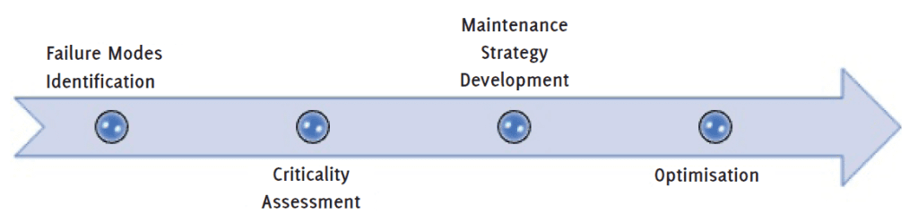
2. Criticality assessment
The first essential task is to determine the criticality of equipment. This will pave the way for how much effort the solution will cost. The equipment criticality assessment process is a method of evaluating asset reliability impact and consequences on the overall business performance. The method is used to rank the criticality of assets relative to each other.
Different pipeline operators will have different methods to determine criticality. Regardless of the method followed, the following four criticality criteria are considered in the assessment: asset failure consequences, asset importance, asset reliability and asset capacity utilisation. Valve criticality is essential to optimise the valve maintenance programmes where critical valves are expected to have more stringent maintenance requirements including frequent inspections and proof testing.
3. Creation of pipeline valve maintenance management strategy
It is necessary to ensure that valve assembly materials (pressure-containing parts, topside and auxiliaries) remain fit for purpose through the life cycle. To achieve this, operators should ensure that they have a well-rounded maintenance management system in place. The system should include the right mixture of maintenance programmes. Figure 3 demonstrates the typical classifications of maintenance programmes.
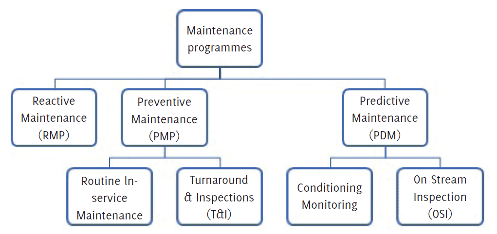
The optimum strategy is to conduct preventive maintenance at fixed intervals, coupled with complete overhauling, where valves are removed from service and dismantled completely for inspection, refurbishment and revalidation through shell, seat and functional testing.
However, with the introduction of on-line inspection tools (instrument scraping) and on-line repair procedures, the odds for pipeline shutdowns being necessary for validation purposes is very minimal. Operators are less flexible to shut down pipelines for T&I purposes. Therefore, to minimise the interruption of the pipelines, a periodical maintenance protocol should be developed with a scope that includes the right maintenance programmes to address all possible potential risks. Table 1 indicates the recommended activities to be performed part of the routine maintenance:
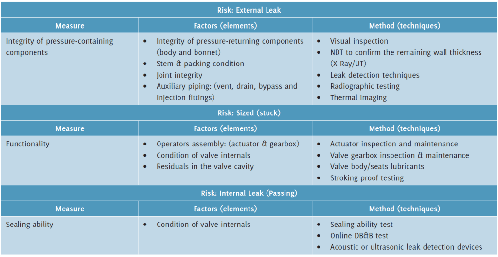
A. Integrity of pressure-containing components
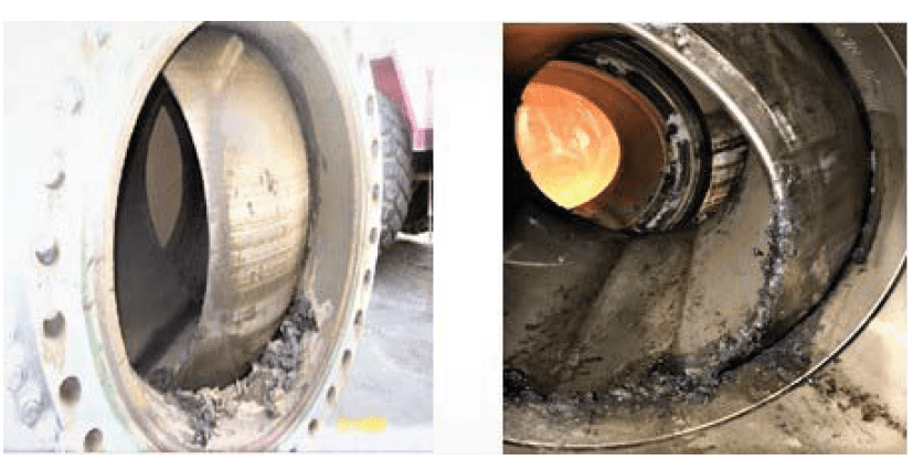
The first risk to be considered is external leakage, as it can pose a direct risk to production, asset, environment and personnel. To mitigate this risk, pipeline maintenance management strategies should include a robust programme for the assessment of pressure-containing components, including body, bonnet, packing system, and auxiliary piping.
Figure 4 demonstrates examples of external leak scenarios in pipeline valves. Visual inspection is the primary inspection method, however, other advanced methods can be utilised including spray soap solution, gas sniffer tests (electronic screening), infrared thermal imaging cameras and ultrasonic leak detectors.
Another factor to be considered for the mitigation of external leakage is the assessment of joint integrity. Especially for larger-sized valves, body joints need to be assessed. Pipelines that experience temperature fluctuations or pressure differences or surges may suffer from bolt relaxation that may later lead to major leaks or failure of pressure containment. Controlled methods (by using calibrated torque wrenches or bolt tensioners, and in a set sequence) of flange tightening should be considered to confirm the torque values of critical flange connections.

B. Functionality
The second risk to be considered is the failure to respond in demand as availability and reliability at the downstream of the failure location may be reduced, which would create potential conditions for major accidents.
In order to confirm the valve functionality, it is essential to conduct a health check for the complete valve assembly, i.e., whether the actuator is capable to provide the required torque, the gearbox is transferring the torque and there is no obstacle to the valve movement.
Valve functionality shall be confirmed through full stroke testing. In case full stroke testing is not feasible, partial stroke testing shall be performed with 10% travel as a minimum; the stroke percentage should be increased if process conditions allow. It is worth to note that partial stroke testing can be used to confirm/verify the valve capability to overcome breakaway thrust/torque.
Partial stroke testing for example, cannot confirm/ verify that the valve will fully seat and it is leak tight. As such partial stroking shall not be considered as substitute to full proof test, instead partial valve stroke testing (PVST) is used to ensure safety function availability without interrupting operation and extending the recommended full proof test interval. A common practice for pipeline operators is to have full stroke testing performed on a 5-year basis or at the test & inspection interval, whichever is less.
C. Sealing ability
The third risk to be considered is failure to achieve the required isolation level in the valve (passing valve). For pipeline valves equipped with a double block and bleed (DBB) feature (refer to API SPEC 6D, Section 3.1.10), the cavity can be relieved via vents or drain connections at the body. The independent upstream and downstream sealing ensure a tight shut-off at the body cavity in fully opened and closed positions.
This allows for verifying the tightness of the ball valve in line via the cavity. For other valve: valves are to be closed in order to check the valve condition, which is not always feasible. The valve condition is to be confirmed through monitoring the pressure buildup downstream or by utilising acoustic or ultrasonic leak detection devices under certain conditions.
D. Preservation
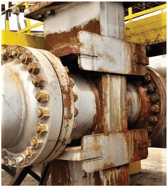
An important element of the valve integrity programme is preservation: this is where valves are to be preserved, so that valve’s performance is maintained until the next PM cycle. The valve’s general condition and integrity of the paint is checked; inspecting for signs of rust (Figure 6), external corrosion, oxidation, external leakages, damage, or cracks. Valve lubrication is an important element in the preservation plan where proper lubrication of valve components can reduce wear, improve durability, and increase dependability.
It can also help preserve valve seal, seat and packing materials to reduce the risks of leaks. Pipeline valves are usually equipped with seat injection fittings to allow lubrication of the internal surfaces and reduces friction at the interfaces. Finally, and whenever feasible, cavity flushing is to be included as part of the preventive programme to help prevent sludge or debris accumulation in the valve cavity. This can help to ensure the valve functions on demand.
4. Data capture and optimisation
A key aspect of managing valve integrity is ensuring that suitable records are maintained; these records can be analysed to identify of area of improvements. The goal is to maintain the valves in a manner that yields the optimum reliability of the asset with an optimum lifecycle cost. Such optimum reliability and cost of the asset can be achieved only through continuous monitoring of the implementation of the integrity programme and drive further improvements. Optimisation includes the scope as well as the frequency. For example, preventive maintenance (PM) of all valves shall be performed once annually. Longer or shorter PM intervals can be reassigned based on the maintenance and operational historical record.
Conclusion
Maintaining equipment is an essential element of pipeline integrity. Valves are mostly overlooked and require full attention. Detailed maintenance of all valves may not be achievable with the finite resources. Therefore, a systematic risk-based approach, considering valve criticality and its potential failure modes and their consequences, is recommended.
About the author
 Mousa R. Al-Harbi is a Valve Engineering Consultant and part of Saudi Aramco Central Engineering. He has a B.S. in Mechanical Engineering from Milwaukee School of Engineering (MSOE), and M.S. degrees in Engineering & Technology Management from the Portland State University, USA. Mousa joined Saudi Aramco in 2002 as a Plant Engineer and currently serves as a Chairman of the Valves Engineering Committee of Saudi Aramco, as well as the group leader of piping and valves.
 Bader Al-Jarallah is a Valve Engineering Consultant at Saudi Aramco Central Engineering. He served as the Chairman of Valve Engineering Standards Committee as well as committee member of several engineering standards. Bader has a B.S. in Mechanical Engineering and M.S. in Material Engineering. Bader joined Saudi Aramco in 2000. Since then, he has dealt with various design, commissioning, operations, troubleshooting & maintenance issues.
References
- Are you using the right sealant for your valves: Valve World Vol. 28, Issue 5, June 2023
- Assessment of Valve Failures in The Offshore Oil & Gas Sector: HSE Research Report 162
- Severe Duty Valve Maintenance Guide; EPRI Project 1011828
- Guidelines for the integrity management of valves for the upstream and downstream Industries: S-1820 ENERGY INSTITUTE, LONDON