Severe service applications in process industries pose unique challenges for control valves, often involving high-pressure drops, abrasive media and extreme temperatures. Selecting the right control valve technology is crucial for maintaining reliability and optimizing performance. This article explores key considerations when choosing control valves for severe service applications.
By Todd Loudin, Valmet
However, other severe service control valves may not be high-pressure but can be considered severe service control because the valves require abrasion or erosion resistance. With abrasive mediums, there are typically two directions to survive abrasive conditions. One is to make internal components harder, and the other is to make internal surfaces softer, so particles bounce off the wear surfaces.
Ceramic control valves and rubberized pinch valves are two types of valves that have high survivability in abrasive mediums. Ceramic valves offer several desirable features that increase valve performance and lifetime. First and foremost, the ceramic valve should not only have a ceramic ball; the inlet and outlet ports should be lined to protect the flow pattern. Otherwise, the ball could direct the flow pattern into the downstream side of the valve body. If the body is not protected by a ceramic lining, the abrasive flow would likely wear through even if the metal surfaces had Stellite coating. Partially stabilized zirconium (PSZ) performs better when wide thermal swings may be present. PSZ ceramics can withstand temperatures from -50˚C (-40˚F) to 200˚C (390˚F); whereas unstabilized ceramics may break or shatter with wide thermal swings.
Metal Matrix Compounds (MMC) are a combination of metal and ceramic or both strength and abrasion. An MMC body adds the strength of steel and the abrasion resistance of ceramic. This can be highly advantageous in extreme scaling conditions. For maximum strength and controllability, the ball and stem engagement of the valve stem should have a blade style to maximize tightness and provide backlash-free control. Low Cv trims in sizes 1” valves may be helpful in low flow accurate control. In extreme scaling conditions, a stainless steel metal matrix body will provide added protection for the valve body. Ceramic valves are applied to the following common applications:
- Lime Mud Control
- Kaolin, China Clay Control
- Carbonate Handling
- Gypsum Handling
- Cement Production
- Metal Slurries
- Autoclaves
- Catalyst Regeneration
- Desulphurization Units
- Pulp & Paper Recausticizing

There are similarities between the rubber-lined pinch control valve and the ceramic control valve. The rubber sleeve in a high-quality pinch valve can also withstand abrasive and erosive flows.
Pinch valves have reduced port sleeves for each valve size specifically designed for process control and tailoring the percent open to provide the most accurate flow control. Pinch valves have some limitations compared to ceramic valves. Ceramic valves are capable of a much higher temperature than pinch valves.
For example, a pinch valve with a high-temperature styrene butadiene rubber sleeve (SBRT) has a minimum temperature of -50˚C (-40˚F) and a maximum of 110˚C (230˚F), whereas the ceramic valve has a maximum temperature of 200˚C (390˚F). Therefore, when the process medium exceeds 110˚C (230˚F), the ceramic valve would be the best choice. A rule of thumb with pinch valves is that 50% of the inlet pressure is the maximum delta P allowed across the control valve is 50% of the inlet pressure. In higher pressure drop applications exceeding 50% of the inlet pressure, the ceramic valve may be the best valve for that application.
Common applications for pinch control valves include:
- Lime Mud Control
- Titanium Dioxide Control
- Mining Applications:
• Flotation
• Thickener underflow
• Hydrocyclones & Magnetic Separation
• Grinding & Screening - Kaolin, China Clay Control
- Calcium Carbonate Handling
- Gypsum Handling
- Cement Production
- Metal Slurries
- Pulp & Paper Recausticizing
Both ceramic ball control valves and pinch valves are excellent in handling extremely abrasive and erosive flows. A pinch valve has the advantage when the valve needs repair; all it requires is replacing the rubber sleeve for the valve to be back in service. The cost of the rubber sleeve is only a fraction of the cost of a new ceramic ball and inlet and outlet liners. However, each customer must determine what they feel is best for their process.

Cavitation and flashing control
All control valves should be sized for process conditions. Sizing programs consider the entered process conditions and calculate the best valve and percent opening to accomplish accurate flow control. Sizing programs detect if incipient or critical cavitation will occur, predict noise levels, and calculate the velocity through the control valve. If the sizing reports higher than recommended manufacturer’s levels, alarms will be displayed. If that occurs, selecting a different size valve or even an alternative valve design may be the solution.
If cavitation is detected, there are special rotary control cavitation control devices that can be deployed. Cavitation occurs when the pressure drop through the valve becomes high enough. When the medium passes over the vena contracta (smallest opening through the valve during control), the medium turns to steam because it dips below its vapor pressure. When the pressure recovers after passing the vena contracta, millions of bubbles implode or collapse causing cavitation. Cavitation is extremely damaging to all types of valves and shortens the lifetime of a valve’s internals.
Newer technologies in rotary control valves employ a tortuous flow path over several stages to reduce the overall pressure drop so that it never dips below the liquid’s vapor pressure.
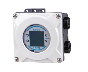
Intelligent positioners offer significant cost and energy
Intelligent positioners have been in existence for many years and the information to end users is often underutilized. More advanced designs reduce air consumption considerably and can save users approximately 90% per year per valve in produced or wasted air consumption. These savings can be significant when there are several thousand positioners in a large processing complex. The greatest advantage of an intelligent positioner is the ability to predict changes in the control valve. These changes may be only minor fatigue, or they could be signaling catastrophic valve failure, which, when detected early, may save the processing unit thousands, if not hundreds of thousands, of dollars annually.
Some valuable features of an intelligent positioner to consider:
- Simple and fast installation and commissioning – autocalibration
- Local/remote operation
- Wide language support
- Expandable architecture
- Hare Protocol rev. 7 and Foundation Fieldbus
- Full suite of diagnostics on every unit
- Self-diagnostics
- Online diagnostics
- History trends
- Communication diagnostics
- Extended off-line test capabilities
- Worldwide support for hazardous area approvals
- Standard Local User Interface (LUI) accessible without opening the device cover
- Distributed Control System (DCS) asset management program
Ideally it is best to select a brand that has the full suite of diagnostic capabilities loaded onto each positioner and can seamlessly interface with third-party assets or performance management systems. The information is always there for the user to access when and whether they ever use the diagnostics. Some positioner manufacturers’ prices increase as new levels of diagnostic capabilities are added, while others load the full suite of capabilities on every positioner for the same price each time.
Conclusion
When dealing with severe service applications involving abrasive slurries, high-pressure drops, or extreme temperatures, it is rarely a good idea to utilize standard valves typically used in clean mediums. These valves often fail frequently, leading to excessive OPEX budgets and increased downtime. Choosing the right control valve technology is paramount to reducing operating costs and ensuring reliable operation.

Ceramic ball control valves and pinch valves have proven to be excellent choices for handling extremely abrasive and erosive flows. While pinch valves offer the advantage of easy repair by replacing the rubber sleeve, ceramic valves can withstand higher temperatures and pressure drops. Ultimately, each customer must determine the best solution for their specific process requirements.
In applications prone to cavitation and flashing, proper valve sizing and the use of specialized trim designs, such as Q-trim in ball control valves, can effectively mitigate these issues. By reducing the overall pressure drop through staged pressure reduction, these technologies prevent the medium from dipping below its vapor pressure, minimizing the damaging effects of cavitation.
Intelligent valve positioners also play a crucial role in optimizing control valve performance and reducing costs. Advanced designs can significantly reduce air consumption and provide valuable diagnostic information to predict valve health and prevent catastrophic failures. Choosing a positioner with a full suite of diagnostic capabilities and seamless integration with asset management systems can lead to substantial savings and improved process reliability.
In summary, selecting the right control valve technology for severe service applications requires careful consideration of factors such as abrasion and erosion resistance, temperature and pressure limitations, cavitation and flashing control, and the benefits of intelligent valve positioners.
By investing time in choosing the correct product, process industries can reduce operating costs, minimize downtime, and achieve greater profitability in their severe service applications.
About the author
 Todd Loudin is Director of Mining and Metals North America, Valmet Flow Control business line, located in Linthicum, Maryland. Loudin has over 30 years of experience working with industrial valves and pumps, mostly with Flowrox pinch and knife gate valves and pumps but several years also Neles valves. He has Bachelor of Science in marketing and executive MBA from Loyola College, Baltimore. He can be contacted at todd.loudin@valmet.com
About this Technical Story
This Technical Story is an article from our Valve World Magazine, August 2024 issue. To read other featured stories and many more articles, subscribe to our print magazine. Available in both print and digital formats. DIGITAL MAGAZINE SUBSCRIPTIONS ARE NOW FREE.
“Every week we share a new Technical Story with our Valve World community. Join us and let’s share your Technical Story on Valve World online and in print.”

