We will also explore limitations of a common fugitive emissions specification (ISO 15848) and how ValvTechnologies has addressed these in the development of the EcoPack® fugitive emissions system for severe service applications. But, before we get there, we must first discuss the difference in quarter turn and rising stem valves.

Article by Tony Majka, ValvTechnologies
___

Quarter turn and rising stem valves

When selecting the most suitable method of stem sealing technique, it is necessary to understand the valve actuation method. Among the most common valve actuation techniques are rising stem (linear) and quarter (1/4) turn. The linear actuation method is found commonly in gate and globe valves, whereas a quarter turn method is typically employed in the ball, plug and butterfly valve types. The actuation technique refers to the method by which the stem or shaft of the product is moved to actuate through the line sealing mechanism.

Refer to Figure 1 for a pictorial demonstration of the quarter turn method of actuation and Figure 2 for the rising stem method of actuation.

The quarter turn method of actuation is often considered to be the more robust design for stem/shaft sealing because the stem is merely rotated about its axis in the stem seal area whereas the rising stem design is rotated about its axis and moved linearly through the sealing area. The linear movement of the rising stem allows for debris and shaft imperfections to generate leak paths as the stem pushes linearly through the seal from inside the pressure boundary to outside the pressure boundary. For this reason, ValvTechnologies utilizes quarter turn valve actuation in most severe service, high-cycling applications. This will be the basis of discussion moving forward.
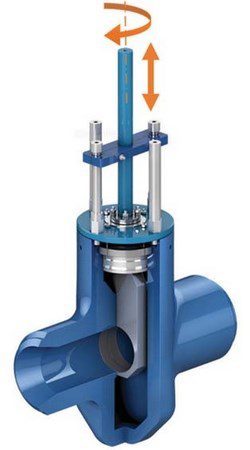
Severe service stem sealing solutions

The definition of severe service has been the center of much debate in recent years. Often, severe service can mean that the media flowing through the valve can be lethal if leaked to the atmosphere. Sometimes severe service applies to media flowing at high-pressure and/or high-temperature. Most commonly severe service is used to define a process media that is highly abrasive or undergoing a phase change while flowing through the valve. All of these can provide a special challenge to valves and their ability to seal both through the line and to the atmosphere.

When chosen correctly, there are many stem sealing solutions in existence that can provide adequate external sealing based on a particular application. A combination of proper selection of seal material and geometry can last many years in service if the valve is appropriately designed. Some of the most common stem seals are made of elastomers (such as Buna, Viton® or Kalrez®), polymers (such as PTFE, PEEK, or special PTFE based blends) or flexible graphite derivatives (such as Grafoil® GTJ, GTK or braided rope). Each of the sealing materials have great properties in certain applications.

  • Elastomer blends have great sealing characteristics and are particularly suited for high pressure, but have lower temperature limitations than graphite and blended polymers and are typically more susceptible to failure in abrasive applications such as catalyst and slurry feed.
  • Polymer blends can withstand more abrasive applications and often have great chemical compatibility. At very high-temperature and pressure these often fall short of performance goals as PTFE really starts to lose its strength around 450°F (232°C) and cannot withstand a fire.
  • Graphite derivatives are generally chemically inert and have very high temperature ranges. Unfortunately, graphite is porous allowing permeation in most emissions tests. Additionally, graphite tends to breakdown in high-cycle applications and extrude from the packing area if the valve is not properly designed. Although its nature does not promote longevity, it is common to find this material utilized in severe service applications due to the high temperature capability and its ability to withstand a fire.
  • For high cycle applications, where stem sealing is crucial, it is common to utilize a mixture of several or all of these in a stem seal.​

The geometry of the stem seal plays a key factor in determining the useful life of the seal. In past decades, it was common to utilize a stem seal that was only an extruded ring of material such as PTFE or Grafoil®. These rings looked like a washer that was compressed into the packing bore to effect a seal on the stem. These seals were prone to extrusion and failure over time. Throughout the years, many geometries of stem seal have been developed to increase the sealing capability and longevity of the stem seal.

The details of each geometry present their own pro and con list, but the key to each of them is to turn the axial compression from packing fasteners into a radial load which seals on the stem without over compressing and wearing too quickly. A common problem with all compression seals is that an end user will observe a leak and attempt to tighten the packing fasteners to stop the leak and often over-compress the packing thus reducing its effective life.
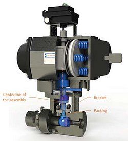
High-cycle serve service applications

High-cycle and fast-acting are commonly used synonymously but they are quite different and have their own design considerations. What is a high-cycle application? End users have pondered this question with varying degrees of definition. Some users may consider 1,000 cycles to be a high-cycle application where some have thought more along the line of 1,000,000 cycles was a high-cycle application.

Among other criteria, it really depends on the type of service, media flowing through the valve and size of pipeline to truly determine what really constitutes “high-cycle”. ValvTechnologies’ rule of thumb is about 30,000 cycles as this is the point when most stem seals fail. This varies a lot based on size, etc. but is a good starting point. Common considerations when working with a high-cycle application are:

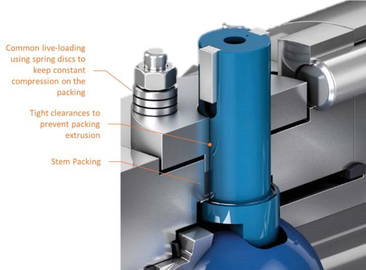
  • Mounting kit design: the stem MUST remain on-center when cycling.
  • Clearance in the packing box: this must be kept to a minimum to prevent extrusion of the packing.
  • Fire safe: does the valve need to pass a fire test such as API 608 or API 6FA? This would require a high-temperature material.
  • Ability to adjust in service: valves are often in difficult-to-access areas which make adjustment difficult and dangerous.
  • Pressure/temperature: this will dictate material selection as well as valve type.
  • Fluid type: if the fluid is dry and/or abrasive it can cause issues.
  • Thermal cycling: will the valve be subject to frequent thermal transients causing it to grow and shrink often?
  • Speed of rotation: if the valve is fast-acting, see subsequent paragraph on fast-acting.

What makes the concept of fast-acting different from high-cycle is the material properties. When dealing with a fast-acting valve, it will be pushing the boundaries of what the materials are capable of handling due to a little discussed property known as the PV limit. The PV limit of a material is essentially the point at which material will begin to substantially deteriorate. The PV limit relates to the pressure and speed at which the surfaces pass across each other and correlates back to when the frictional heat will create microscopic melting/galling.
When valves are used for emergency shut down, they may exceed PV limits but only for a short time and only cycle every few months or even less in most cases. When you connect fast-acting with high-cycle you need to really worry about the soundness of an engineering design. Many materials if not designed, machined and coated properly will fail at this point.

EcoPack® engineered solution by ValvTechnologies

When ValvTechnologies introduced the original PulseJet valve years ago, we employed a blended combination of braided graphite rope and PTFE. The design was intended to last roughly 100,000 cycles with routine adjustment to the packing. A stack of spring discs was utilized to maintain constant compression on the stem seals through wear and thermal cycling. Special considerations were given to the overall valve design and material configuration to achieve such highperformance. What made this product so unique was the pulsejet application itself.

  • The application was to “pulse” hot syngas (a flammable and lethal gas if inhaled). Atmospheric leaks are hazardous in multiple ways.
  • The product operated at 1640 psig (113 barg) with temperatures of 475°F (246°C) while cycling from closed to open to closed in 0.45 seconds.
  • The valve would dwell in the closed position for roughly 90 seconds then operate again.
  • This continued for four months before any maintenance could be performed without the system running.
  • There was no question that this was severe service.

Although the first-generation pulsejet design had proved to be successful, ValvTechnologies found an area where the product could greatly improve by working with their customers. The routine adjustments to the packing arrangement were observed to be difficult, dangerous and improperly executed. This could cause the packing to unevenly and prematurely wear. Partnered with our customer, ValvTechnologies commenced a program to develop a solution which could make the entire four months (125,000 cycles target) without a need to adjust the packing.

This would reduce the number of times employees were in harm’s way and reduce volatile emissions into the environment. When ValvTechnologies began this endeavor, they needed a measurement criteria for stem leakage. We decided to utilize one of the most common and widely accepted fugitive emissions tests, ISO 15848 for measurement. When developing our test, we had to make some test modifications because even ISO 15848 did not effectively simulate the test they were performing.

After partnering with several vendors and running through many iterations of product design, the Special Projects team at ValvTechnologies came up a configuration which greatly exceeded the results we were seeking. Through painstaking efforts, the team was able to employ special materials, coating technology and a unique seal combination of filled PTFE, PEEK and graphite (known now as EcoPack®) to allow our customer to make it to an eight-month turn-around plan.

In late 2015, ValvTechnologies announced the offering of the EcoPack® technology which has been specifically designed for high-cycle applications of over 250,000 cycles without adjustment. The EcoPack® technology is a stem-sealing solution designed to seal at line temperatures of up to 450°F (232°C). The assembly is tested to be fire safe and shows excellent compatibility with syngas.
The EcoPack® design does not require traditional live-loading utilizing spring discs, therefore, the gland is held stationary and flush with the bonnet. This solution means the packing does not require adjustment during operation, reducing site safety concerns and need for continual maintenance. This design uses pressure from the process to provide adjustment with an integral spring load for low pressure. The EcoPack® system has been introduced in the ValvTechnologies, NexTech® 2nd generation pulsejet valve, a two-piece trunnion mounted ball valve. Through successful lab testing as well as field tests well in excess of anything before achieved in this service, ValvTechnologies now has multiple installations utilizing this sealing technology.
Throughout the course of the EcoPack® development, ValvTechnologies proved several design theories while we established new ones. We set out to develop a new type of stem seal and wound up engineering a superior sealing system.

Table


About the author

Tony Majka is Director of Engineering at ValvTechnologies, responsible for research and development, product development and design, manufacturing, production and application engineering, as well as leading the engineering process continuous improvement and product standardization programs. Majka joined the company in March 2015. Prior to joining ValvTechnologies, he served as manager of valve product engineering and research and development for Flowserve Corporation in Cookeville, Tennessee where his responsibilities included oversight of the India engineering design center.

Figure 4: Stem Sealing close-up

Previous articleSeries VFCR Visi-Float acrylic flowmeter release
Next articleInnovative gearbox provides vital subsea maintenance fu