
This article provides essential technical insights for improving the leak-tight reliability of bolted flange connections by addressing critical factors in gasket tightness, torque wrench motion, washer selection and bolt loading considerations.
By Randy Wacker
Bolted flange connections (BFCs) play a critical role in ensuring the safe and efficient operation of various industrial systems. However, achieving reliable leak-tight performance can be challenging, as numerous technical factors must be considered. Drawing from the author’s extensive experience teaching an ASME course on bolted joints and gasket behavior, this article explores essential considerations that are often overlooked or underestimated in the quest for leak-free BFCs.
The importance of gasket tightness, torque wrench use and motion, washer selection, and bolt loading are examined in detail, highlighting their individual contributions to the overall integrity of the BFC. Understanding the impact of these factors is crucial for minimizing leaks, enhancing safety, and improving operational efficiency. This article provides a comprehensive overview of the key elements that influence the leak-tight reliability of bolted flange connections, enabling informed decision-making and better results in industrial applications.
Gasket tightness
Gasket tightness is a critical factor in the leak-tight reliability of bolted flange connections (BFCs). While this topic has been covered in previous ESA articles in Valve World, its inclusion here is essential due to its significant role in mitigating the release of harmful toxins and carbon emissions into the atmosphere. The potential exposure to carcinogens may be a serious concern for employees working in plants that process dangerous chemicals. Increasing ‘tightness’ in BFCs directly correlates with reducing leakage. Given the well-established science of sealing gasket materials, it is crucial that the design of a BFC begins with identifying the gasket stress required for reliable and safe sealing. Europe has long recognized this responsibility and has successfully elevated both a gasket testing protocol (EN 13555) and BFC design requirements (EN 1591-1) to engineering code status. These codes ensure that the BFC can structurally withstand the forces involved in achieving the desired level of gasket tightness. Outside of Europe, the Pressure Vessel Research Council (PVRC) method serves as an additional gasket leak-tight testing protocol. Although substantially different in detail from EN 13555, the PVRC method also provides information that can be used to ensure a specific degree of gasket tightness.
EN 13555 defines the necessary measurements, pressure, and temperature conditions to validate a gasket material’s sealing capability and its structural integrity limits. This standard enumerates gasket elasticity, creep relaxation factor, maximum allowable gasket stress, and minimum required gasket stress for a particular class of tightness. The testing even determines the extent, if any, to which the gasket material may extrude into the process flow area and includes limits.
EN 1591-1 provides an evaluation method to determine the component strength criteria needed to safely ensure the targeted gasket stress is applied to the connection. This standard goes beyond considering only pressure, temperature, and bolt load, and includes other effects such as component deformation, bolt load scatter from various tightening methods, external axial forces, bending moments, and differential thermal expansion between components.
PVRC
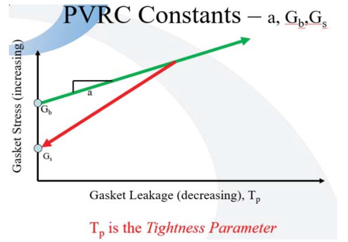
In 2018, the ASTM F03 Committee elevated the PVRC leak-tightness gasket testing protocol to code status as ASTM F2836-18. Although this protocol differs significantly from EN 13555, it has a long and successful history of use when designers are well-versed in the capabilities of ASME flanges. Figure 1 illustrates a typical PVRC tightness testing protocol, where Gb, Gs and and ‘a’ are used in the tightness calculation.
The successful use of the PVRC method dates back more than 30 years. E. I. Dupont, a major contributor to the funding of its development, quickly utilized this information to check bolt strength against the gasket loads required for reliable BFC sealing. In some cases, this resulted in exceeding ASME design values. As discussed in an earlier article¹, justification for this approach was found in ASME Section VIII, Division 1, Appendix S, which states that “an initial bolt stress higher than the design value may and, in some cases, must be developed in the tightening process.” The appendix also suggests general provisions for this practice.
Currently, ASME has not yet incorporated leak-tightness into the basis of flange design³. When this integration occurs, it is expected to lead to substantial improvements in mitigating toxic and carbon emissions. In the meantime, the designers must rely on their own judgment and experience when applying these loads to ASME flanges.
Torque wrench motion
Speed
An often underappreciated factor in accurate torque application is the consequence of wrench motion on the torque indicator’s reading. The accuracy of the indicator relies on the kinetic friction during bolt tightening, which requires the bolt to be in motion, but not too quickly. If the motion is applied too rapidly, the indicator will ‘sense’ the inertial force from the rapid movement, resulting in an overstated value of the applied torque. When a tightening professional has not been properly trained in this consideration, it is not uncommon, particularly when using a ‘click’ type torque wrench, to use a jerking motion to quickly attain a ‘click.’ This can lead to the actual torque applied being significantly lower than the expected value.
Start-stop
To illustrate this effect, consider an example where a bolt is carefully tightened to its targeted value for a given tightening pass. When the wrench is returned to this location, it may indicate a higher value than the previous pass, even if some relaxation of components has occurred. A primary reason for this is that the wrench initially senses the effect of static friction, which is higher than dynamic friction. Consequently, the indicated value at the moment of first motion will be above the value when motion is established.
Through-hardened washers
There is an important distinction to be made between a ‘hardened’ washer and a ‘through-hardened’ washer. A hardened washer is only surface hardened and very often lacks the strength to resist bending or cupping from the bearing force of the nut. This bending increases friction loss as the edge of the nut digs into the deformed washer, resulting in less of the indicated torque being transferred to the bolts. In contrast, a through-hardened washer is hardened to its full depth, eliminating or minimizing this friction loss and further reducing friction due to its relatively smooth surface compared to not using a washer at all. Through-hardened washers also protect the flange face from damage caused by the nut. If there are markings on one side of the washer, the marking side should always face towards the flange.
Further, when through-hardened washers are deployed the effective length of the bolt is increased. This additional length, for a given bolt load, increases the elastic energy available to the gasket which in turn helps to maintain stress on the gasket as it undergoes axial deformation.
Bolt loadings
Field engineers, without the benefit of EN1591-1, are often called upon to evaluate the value of bolt force needed to acquire the value of gasket stress as provided by a gasket manufacturer. It is important that the manufacturer, or someone experienced in the methodology has performed a formal leak-tightness calculation and included a check against a blow-out condition.
Given the value of gasket stress, its area, and the number of bolts, the required force on a given bolt can be easily determined using the following expression: Fᵦ = σg Ag /Bno’ where σg is the gasket stress, Ag is the gasket area and Bno is the number of bolts. It is important to emphasize that the bolt force calculated using the provided expression is not the only force to consider when applying the bolt load. The following is a list of additional considerations that the designer should take into account to ensure a reliable and leak-tight bolted flange connection.
Fatigue
Fatigue can be either high-cycle and low-stress, or high-stress and low-cycle, with the latter being more likely in a BFC. Failure to recognize the endurance limit of the bolting can result in bolt failure at a stress level that would not typically be expected to cause problems. VDI 2230 is recommended as a valuable resource for considering fatigue in bolted flange connections.
Bolt bending
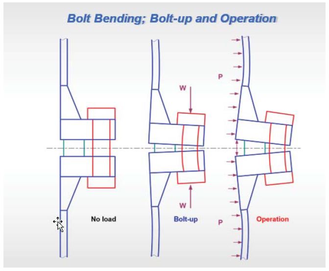
Regardless of the magnitude, there will always be some degree of bolt bending due to flange rotation. This bending increases the tensile stress on one side of the bolt while decreasing it on the opposite side. The added stress on the tensile side of the bolt should be considered when evaluating the stress limit on the bolting material. Figure 2 illustrates the typical effects of bolt-up and operation on bolt bending.
Piping movement
Piping movement, caused by various factors, can also introduce stress to the bolting; sometimes significantly. To formally assess this consideration, a ‘flexibility analysis’ should be conducted. The designer is cautioned that even if this analysis was performed, it’s not unusual that piping design changes and/or deterioration of piping supports may have occurred over time. A walkthrough inspection of the area can sometimes be invaluable in determining if greater attention to this consideration is warranted.
Flange fit-up
Poor flange fit-up, also discussed in detail in an earlier ESA article2, can result in the addition of shear, bending, and/or tensile loading on the bolting. The best protection is to strictly comply with the limits provided in the applicable engineering standard. Experience suggests that, second only to not following a formal leak-tightness based tightening procedure, this challenge is a common cause of BFC leakage. It is crucial to understand that a torque wrench cannot differentiate between the force intended for the gasket and those that might result from pulling, bending, twisting, and/or shearing due to poor flange fit-up.
Key takeaways
While numerous other considerations can impact the successful leak-tight condition of a BFC, this article has focused on some of the most critical factors as well as addressing some of the lessor known, but also important ones. For those who face the daily challenge of improving plant safety and protecting the environment from the increasingly severe consequences of hazardous emissions, it is hoped that this list and their brief explanations provided will be useful in acquiring, maintaining, and troubleshooting reliable gasket sealing to the degree of gasket tightness warranted by the process service. Ultimately, ensuring the integrity and leak-tightness of bolted flange connections is a responsibility shared by all stakeholders involved in the design, installation, and maintenance of these critical components.
Sources
- ESA article entitled “A Brief History of ASME M and Y Factors,” June 2023.
- ESA article entitled “Primary Flange Forces – Part 2,” May 2016.
- As a member of the ASME Special Working Group tasked with introducing the concept of leak-tightness into ASME code, completion is expected within the next couple of years.
About the author
Randy Wacker, a professional mechanical engineer with over 40 years of experience, specializes in the design and specification of leak-tight bolted flange connections and is presently the Senior Consultant for Inertech, Inc. He is an ESA member, has consulted the American Society of Mechanical Engineers (ASME) in the development of engineering standards, serves on ASME committees, and has rewritten and taught the ASME course on Bolted Joints and Gasket Behavior.
About this Technical Story
This Technical Story is an article from our Valve World Magazine, August 2024 issue. To read other featured stories and many more articles, subscribe to our print magazine. Available in both print and digital formats. DIGITAL MAGAZINE SUBSCRIPTIONS ARE NOW FREE.
“Every week we share a new Technical Story with our Valve World community. Join us and let’s share your Technical Story on Valve World online and in print.”