Widely applied and appreciated in gas turbine use, high-pressure recovery control valves have however yet to make any real inroads in other applications. In his latest article, control valve expert Hans Baumann explains the function, test results, and advantages of this valve concept which, he believes, could be of real benefit in other industrial sectors.
By Hans D. Baumann

High-pressure recovery valves (see Figure 1), have been used for quite a number of years as fuel control devices to regulate gas flowing to burners of gas-turbine generators.
Such valves bring significant benefits. For example, the most important feature of this valve is the great energy savings it offers. The device can control large amounts of liquids or gases whilst sacrificing only limited amounts of pressure drop – just 10 per cent of inlet pressure for gases, for example. Also of interest is the unique function of this device to be able to operate within a significant range of pressure reductions and within a laminar flow regime. This flow regime experiences no turbulence, nor the associated sound.

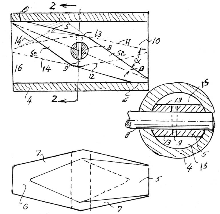
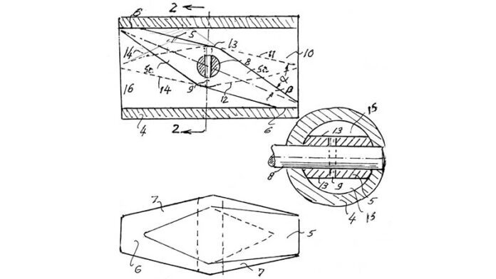
The question arises, why hasn’t this concept been employed in general industry? The answer may simply be a lack of familiarity. In order to provide a viable alternative for general use, the author has therefore designed a special valve type as shown in Figure 2.
Description of the device
As Figure 2 shows, the design is quite simple and lends itself to low-cost manufacturing. There are only three moving parts. The appearance draws itself to a butterfly valve. Yet, this vane does not close in the vertical direction, but is tilted about 30 degrees from the horizontal axis.
Significantly, in this position, all side surfaces along the vertical axis are in contact with the inner wall of the housing in order to provide shut-off, thus providing a tilted wall across the housing (see also the vertical view in Figure 2).
The reason for tilting the vane is to provide an overall length which is twice that of a comparable vertical vane. The result is that all planar surfaces are located less than 20 degrees (α) from the vertical axis, thus providing sufficient pressure recovery. Unfortunately, nothing is perfect.
In this case, the device cannot meet Class IV leakage (although it will meet Class II). In addition, the travel is limited to 30 degrees. This means that the shaft will need a 2” extended lever to satisfy 1” actuator travel. On the other hand, with such high leverage and low operating torque, a 25 square inch actuator would be able to operate a 4” valve.

Test results
A 2” prototype was built and submitted to the Water Research Lab at the University of Utah for evaluation, using water as test medium. Here are the results:
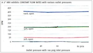
Rated Cv = 60, Fl at 100% travel = 0.72, Fl at 20% travel = 0.63, Xfz = 0.35 at 100% travel and 0.49 at 20% travel. Instability at 100 psig inlet and o psig outlet = none. Torque: nil, not measurable. Choked flow occurred between 19% to 22% of inlet pressure (equivalent choking gas at 9.5 to 11% of P1). Resultant flow downstream stayed constant within +/-2% as indicated in Figure 3.
Sound level measurements
A microphone was placed downstream of the test specimen during most of the test runs. Figure 4 shows the results of a typical test run. The sound levels were exceptionally low. Part of the reason was that about one third of the pressure range happened to be in the laminar flow regime. Fluid mechanics tells us that, in a laminar flow regime, there can be no turbulence, hence, no sound.
In order to dramatize the about 14 dB sound reduction, the author plotted the sound emitted from a conventional butterfly valve having the same data input. See Figure 4. Once the choked flow induced constant flow and velocity is achieved, the only constant sound level comes from turbulence inside the downstream pipe, which typically only measures 70-80dB.
Higher levels can only be expected from the final pressure drop at the end user.

Adherence to acoustic laws
Assuming Xfz = 0.35,
Xy = 0.675:
The first stage:
Lp1 = 30 log(1 / 0.5Xfz) = 22.7 dB
The second stage: Lp2 = 10 log(Xfz / 0.5 Xfz) = 3 dB
Third stage:
Lp3 = 60 log(Xy / Xfz) = 17.1 dB
Fourth stage:
Lp4 = -60 log( X/ Xy) = -10.2 dB
With the basic sound level (A + B) from the ‘Baumann ABC’ method = 57 dB, then we can find a maximum noise level to occur at Xy, which then is 57 + lp1 + lp2 + lp3 = 57 + 22.7 + 3 + 17.1 = 99.8 dB (Figure 4 shows 99 dB).
Note, that the line between 0.5Xfz and Xfz in Figure 4 is linear, which proves that there is laminar flow; hence the 10 log in Lp2.
The data indicates that there is a 3dB increase in external sound in the second stage, even though laminar flow cannot produce sound. The real reason is, that in this region, the pipe transmission loss decreases by 3dB due to orifice velocity changes between 0.5 Xfz and Xfz.
Note: While the above data is based on measurements with water, using fluid mechanic laws, there should be no appreciable differences if such a valve is used for gaseous fluids as long as FL2 is substituted for Xfz.
Applications
The range of applications for this device include:
- Pressure reduction for gases and liquids (with reduced cavitation effects)
- Fuel flow control for oil and gas to burner nozzles
- Pump cavitation avoidance
- A steady flowing quantity regardless of tank level makes it ideal for the filling of tanks
- Pump discharge pressure regulator
- Constant flow through fire hoses regardless of altitude
Conclusion
The above data demonstrates that high-recovery valves can be a viable alternative to conventional control valves since they do not depend on high turbulence for fluidic energy conversion. The author hopes that this article may inspire others to revisit the high-pressure recovery valve and develop it for the benefit of other applications.
About the author
 Dr. Baumann, a former President of the Baumann valve company and a former VP of Masoneilan and Fisher Controls, is now an international consultant. He is credited with 106 US patents and has authored 140 publications and eight books, including the Control Valve Primer now in its fifth edition. Dr. Baumann is an Honorary Member of ISA and a Fellow Member of ASME. He can be reached at hdbaumann@phbinc.net.
References
“A simple aerodynamic noise estimating method-why not”, by Hans D. Baumann, VALVE WORLD, issue 10, November 2016 (copies available from the publisher).


