Hydrometallurgy is typically divided into three general areas:
1. Leaching: The leaching methods are in-situ, heap, vat, tank, and autoclave.
2. Solution concentration and purification: The methods are solvent extraction, Ion exchange.
3. Metal recovery: The methods are electrolysis and precipitation.
Leaching involves the use of aqueous solutions to extract metal from metal bearing materials which is brought into contact with a material containing a valuable metal. The lixiviant solution conditions vary in terms of pH, oxidationreduction potential, presence of chelating agents and temperature, to optimize the rate, extent and selectivity of dissolution of the desired metal component into the aqueous phase. Through the use of chelating agents, one can selectively extract certain metals. Such chelating agents are typically amines of schiff bases. After leaching, the leach liquor must normally undergo concentration of the metal ions that are to be recovered. Additionally, undesirable metal ions sometimes require removal. Metal recovery is the final step in a hydrometallurgical process. Metals suitable for sale as raw materials are often directly produced in the metal recovery step. Sometimes, however, further refining is required if ultra-high purity metals are to be produced. The primary types of metal recovery processes are electrolysis, gaseous reduction, and precipitation. For example a major target of hydrometallurgy is copper, which is conveniently obtained by electrolysis copper ions reduced at mid potentials, leaving behind other contaminating metals such as Iron and zinc.
Knife gate valves in mineral processing
The mineral processing industry uses knife gate valves, they nearly always think of a low pressure MSS-SP-81 & MSS-SP-148 and many more which are used successfully in mining. The distinction needs to be mining, not mineral processing. The
push-through knife gate’s design works exceedingly well in low pressure, low cycle, and neutral pH applications where its discharge causes no problems. However, this cannot be said when the applications are corrosive with acidic solutions, have higher cycle frequencies, and higher pressures.
Whereas Pressure Oxidative Leaching (POL) and Pressure Oxidation (POx) or one can say Pressure Acid Leaching (PAL) as well as Atmospheric Leaching (AL). In the case of the POL project, if engineering design pointed to a decision to use a push-through style of knife gate valve per MSS-SP-81 it would be problematic, specifically in any of the acidic services where the valve is required to cycle; every cycle produces a discharge and more cycles produce greater discharge. The nature of the push-through knife gate design allows the body to be constructed of a material that does not necessarily have to be resistant to the process fluid, as the valve’s elastomer sleeves fully isolate the body from the process. That observation is valid when the body is not subjected to corrosive attack from valve discharges or leaks from the valve itself or surrounding equipment.
If an engineer were to continue using the original valve codes that were developed to identify push-through knife gates suitable for low pressure application per MSS-SP-81 and MSS-SP-148, a bidder with experience in hydrometallurgy and offering a style of valve where the body was in contact with the process only had the gate material to use as a key to body material selection per MSS-SP135 (high pressure high temperature for erosive and corrosive minerals application) or in the case of a lined knife gate, a resistant body liner that acted like the sleeves of a pushthrough protecting the valve body from corrosion.
This means that a valve with a titanium gate must have a titanium body; our twenty years of experience has clearly shown us that push-through or lined knife gates suffer a very high percentage of failure and OPEX is far higher than a properly selected knife gate to high pressure severe service applications per MSS-SP-135 and MSS-SP-146

Detailed technical products in compliance pay particular attention to the actuation selection. We have seen countless numbers of valves in the field where the cylinder is far too small to power the valve open or closed on demand due to the significant changes that occur on valve thrust while in service. In addition, our company’s philosophy to apply a robust safety margin for thrust was the result of seeing valves in actual service and the knowledge that a successfully automated valve is one that continues to provide the closing or opening power at the end of the valve’s useful life; not only when it is new.
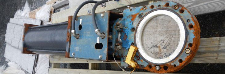
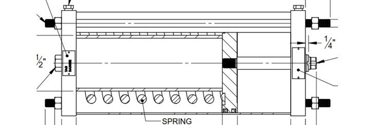
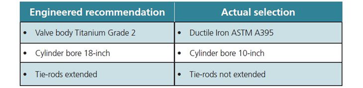
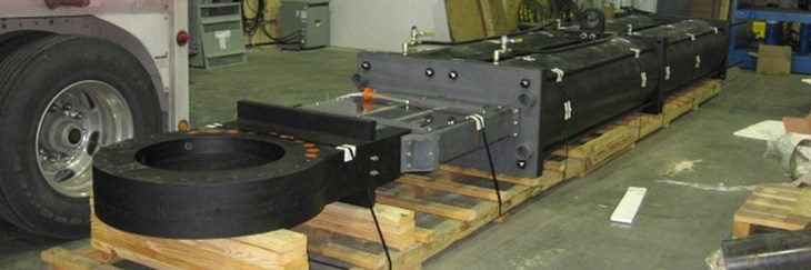
When the actuator is a spring cylinder, this is even more important, not only from a valve operation point of view, but also from a safety perspective when cylinder seal replacement is necessary. The cost savings from using a ductile iron body with a Teflon liner is false economy when they fail in a short time frame. The 10-inch lined valve shown in Figure 1 was the size of the bore of the spring return cylinder, and lacked extended tie-rods that would allow a safe decompression of the spring when undoing the cylinder tie-rods in order to replace the pneumatic piston and rod seals during maintenance. Comparing the valve in Figure 1 with what we consider engineered knife gate provides these differences:
One other significant difference between a lined knife gate and an engineered guided shear gate is the very specific need for load distribution and filler rings and gaskets that the commodity knife gate valves require when installed in certain types of pipe. Flange gaskets are required for some piping and not for others. Filler rings are required with every lined knife gate valve, load distribution rings are required with rubber-lined or PTFE lined piping, but not with FRP piping. The load rings are 0.50 inches thick and when required are used on both sides of the valve, adding 1.0 inches to the valve face to face (which makes them non-compliant with B16.10, MSS-SSP-81, MSS-SP-135).
Engineered guided shear gates
The level of complexity of installing a lined knife gate valve into the various pipes and obtaining the proper filler ring height is high and requires a detailed user data matrix for each valve size and connection type as well as a substantial dedicated inventory of rings and gaskets. The added time it takes to install these valves is substantial as would mistakes. Engineered guided shear gates require no special rings and mate conveniently against both flat and raised face flanges with simple standard gaskets – no load or filler rings required.
Some of these common issues occur in another case whereby acidic discharges damages the valves as well as surrounding equipment and building structures including the floors; as well as automated valves not being able to fully cycle open or closed. Push-through knife gates either freely discharge the process on every stroke (a discharge that grows with the number of cycles and age of the elastomers) or the discharge can be contained with the addition of a discharge containment plate or drainage system. If you add a containment plate or system to control the discharge, you need to ensure the materials are compatible with the process fluid. If acidic, the body needs to be corrosion resistant as well. This defeats the cost advantage of using the sleeves to protect the body from corrosion, as does the cost of the containment system.
Understanding the cycling duty
Beyond the standard information of size, connection, piping material, media, temperature, pressure, actuation and selected body and trim materials, it is essential to have a deeper understanding of the required cycling duty of the valve and the media. SSIVs are not just pieces of pipe; isolation valves have a dynamic phase when they cycle and if this dynamic phase is not fully understood, one cannot fully appreciate what the consequences can or will be. The media may have very different characteristics when flowing normally or when stopped. These conditions not only occur during the valve’s Normally Open or Normally Closed positions; but depending on the types of valves, can occur in trapped cavities within the valve.
If you don’t analyse carefully what these changes can do for the valve’s operating thrust or torque, you run the danger of under-powering the actuators selected and then having a valve that cannot provide the duty it was designed to. There are no universal hard and fast rules on cylinder sizing; one uses the basic information provided on the valve datasheet: Valve Size, Line Design Pressure, Shut-Off Pressure, Media (to ascertain a media factor for sizing), Actuator Power Supply (pneumatic, hydraulic, electric), and Actuator Action. Engineered mining sites/mineral plants with leaching units need to be very conservative with actuator sizing i.e. apply five media factors (Lubricating, Clean and Clear, Mild Slurry, Severe Slurry, Scaling) to the torque or thrust of a new valve based on the design pressure load on the valve and using the lowest power value if there is a range, e.g. 80 for 80-120-psig air supply or 1500 for 1500-3000-psig hydraulic supply.
Further apply a generous safety factor to ensure the valve will cycle on demand after it has been installed in the application and aged due to its normal functioning. This safety factor does have a cost impact but it has led to a history of 100% success of availability of the valve on demand. This in turn has led to obtaining the first SIL 3 approval from Lloyd’s for a knife gate valve.
We need to have better communication to reach the best technical solutions with teams of engineers involved on a mining/leaching project. All too often, the valve industry does not communicate clearly and the best practice doesn’t get executed. We have learned and witnessed that the application demands certain valve types and options. A valve expert always says “the application dictates the valve.”
We are sure there are no badly made valves, nor any perfect valves, and we are just as sure that there are valve types and designs that are best suited for the needs of the process. For hydrometallurgical plants, we have overwhelming evidence that pushthrough knife gates should not be used on applications that are acidic, require a reasonable number of cycles and operate at higher pressures; or for alkaline applications that exhibit substantial solids deposition.
Guided shear gates have the most features and best fundamental design to operate in these challenging conditions and provide the greatest degree of success. They are no more expensive than other knife gate types when all parts of the valve design are compared to the same parts of the other valve types that are required to operate successfully for a number of years. Understanding how valves operate, perform, and what the application needs is vital to selection; as is clear communication.
Gobind Khiani, P.Eng., is a Lead Discipline Engineer at Fluor Corporation, Canada and writes regularly for Valve World.