This article discusses the reasons why it is incorrect and potentially dangerous to install ASME Section VIII pressure relief valves on boilers designed to ASME Section I standards, highlighting the critical differences between the two valve types.
By Artur Cardozo Mathias
Meeting the requirements of the ASME Code Section I
A common mistake observed in some industries is the use of pressure relief valves designed according to ASME Code Section VIII on boilers constructed to ASME Code Section I standards.
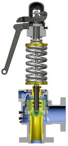
Valves designed to meet ASME Section I requirements are subject to more stringent criteria compared to those designed for ASME Section VIII. As a result, the engineering of these valves is more complex to satisfy these requirements. For instance, ASME Code Section I limits overpressure to 3% or 2 psi, whichever is greater, while ASME Code Section VIII allows for 10% or 3 psi, whichever is greater. If a pressure relief valve is set to open at the same value as the boiler’s Maximum Allowable Working Pressure (MAWP), the higher overpressure permitted by ASME Section VIII (10%) would exceed the maximum accumulation allowed by ASME Section I (6%).
Blowdown is another parameter with more stringent requirements in ASME Section I compared to ASME Section VIII. Although blowdown values are no longer required from the end user and are only necessary from the manufacturer during the valve flow capacity certification testing phase, ASME Section I specifies maximum blowdown values between 4% and 6%, depending on the valve’s adjustment pressure range. In contrast, ASME Section VIII has a fixed maximum blowdown value of 7% or 3 psi, whichever is greater, for gases and vapors. Therefore, the primary reason why a valve designed according to ASME Section VIII Code should not be installed on a boiler designed to ASME Section I standards is that the ASME VIII pressure relief valve fails to meet the mandatory minimum overpressure and blowdown requirements.
ASME Section I mandates a minimum blowdown of 2 psi or 2% of the set pressure to ensure consistent, chattering-free valve operation. In contrast, ASME Section VIII does not require a minimum blowdown. In boiler valves, a blowdown of less than 2% or 2 psi can cause the disc to hit against the nozzle and the flow direction at the same opening pressure value, resulting in no disc elevation stroke.
Consequently, the valve fails to release the required flow capacity, further increasing the pressure inside the boiler. Chattering can damage valve components, valve fasteners to piping, and adjacent piping.
More complex engineering in boiler valves
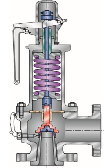
In an ASME VIII valve, maximum flow capacity is achieved at 10% overpressure or 3 psi, whichever is greater. If the overpressure value is reduced to 3% to attempt to meet the ASME Section I requirement, the minimum required nozzle area increases. As a result, the ASME Section VIII valve cannot reach the full lifting stroke of the disc and, consequently, cannot achieve its maximum flow capacity at 3% overpressure.
Pressure relief valves designed for boilers, owing to their more complex engineering, can achieve their maximum flow capacity at a lower overpressure value compared to valves designed and built in accordance with ASME Code Section VIII.
Comparing both designs further, consider an L orifice valve with a nozzle passage area of 2.853 in2. The total disc elevation stroke is equivalent to 25% of the nozzle throat diameter. When this stroke percentage is reached, the area formed by the nozzle throat and the area formed by the total elevation stroke of the disc are equal. Consequently, the valve’s flow capacity is physically limited by the nozzle throat area rather than the disc’s lifting stroke. In this example, for a nozzle with an L orifice equivalent to 48.4 millimeters in diameter, the 25% lifting stroke of the disc is 12.1 millimeters. In other words, the nozzle throat area and the area formed by the total lifting stroke of the disc are both 1839.9 mm2. Even if the disc stroke were higher, the valve’s flow capacity would still be limited by the nozzle throat area. Theoretically, both designs (ASME Section I and ASME Section VIII) achieve the same maximum total disc elevation stroke value, but at different overpressure values, resulting in different flow capacity values.
The nozzle area value in the above example is an effective value defined by API Std. 526, which is primarily applied to valves that protect pressure vessels constructed in accordance with ASME Section VIII. However, actual manufacturers’ values may be slightly larger than those published by API Std. 526. Many boiler valve manufacturers use only some of the orifice area values published by API Std. 526 as a reference, but the sizes (NPS) of the input and output connections do not follow the values defined in the API. Therefore, center-to-face dimensions on valves constructed in accordance with ASME Code Section VIII, as defined in API Std. 526, are not reference values for boiler valves. In boiler valves, these center-to-face dimensions are individually standardized by the valve manufacturer; however, there is no standard that standardizes those dimensions similar to the API.
Overpressure and blowdown
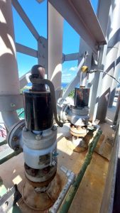
A higher overpressure (according to ASME VIII), combined with a higher blowdown value, leads to greater steam waste during the relief process. Simultaneously, it exposes the boiler to higher pressure and temperature, potentially causing thermal damage. Consequently, greater blowdown requires the boiler to produce more steam to replace the wasted steam. In contrast, a pressure relief valve designed and built to meet the requirements of ASME Code Section I, with more complex engineering, provides lower overpressure and lower blowdown. This results in less exposure of the boiler to pressure and temperature and minimizes the waste of produced steam.
The maximum relief pressure through the valve (at 10% overpressure) will also be the maximum pressure inside the boiler. Lower overpressure and blowdown also prevent elevations in the water level in the boiler’s steam drum, which could cause water to be “carried over” into the internal components of the pressure relief valves when they open during operation.
To further illustrate this point, we can compare the flow capacity values with equal set pressure values and the same nozzle passage orifice, but with different overpressure values. The relief pressure (opening pressure + overpressure), beyond the actual passage area of the nozzle orifice, determines the valve’s flow capacity. By changing the overpressure value, the relief pressure value is also changed, consequently altering the valve’s flow capacity at 3% or 10% overpressure.
Example 1:
Boiler pressure relief valve set to open at 300 psig (20.7 barg) with 3% overpressure and “M” (3.6 in²) orifice:
- Absolute relief pressure: 323.7 psia (22.3 bara)
- Valve rated flow capacity with saturated steam: 52,692.27 lbs/hr (23,887.56 kg/h)
Example 2:
Pressure vessel pressure relief valve set to open at 300 psig (20.7 barg) with 10% overpressure and “M” orifice (3.6 in²):
- Absolute relief pressure 344.7 psia (23.7 bara)
- Flow capacity with saturated steam: 56110.7 lbs/hr (25437.26 kg/h)
Specification and sizing responsibilities
The requirements of Sections I and VIII differ based on who is responsible for installing the pressure relief valve. For new construction, in accordance with Section I requirements, the boiler manufacturer is responsible for specifying and sizing valves by completing ASME Forms P-7, or occasionally Forms P-2, P-3, or P-3A (refer to paragraph PG-112.2.8 of ASME Section I, as well as PG-16.2.4 and PG-70.1). The boiler manufacturer is the one who possesses the information regarding the boiler’s vaporization capacity.
In contrast, for pressure vessels, the responsibility for selecting and installing the pressure relief valve or other pressure relief device (see UG-125(a) 1 through 4 in ASME Section VIII editions through the 2019 edition or paragraph UG-151 (a to c) in the 2023 edition) lies with the end user, as they hold the information about their process. The vessel manufacturer is not required to provide the overpressure protection system (refer to ASME Code Section VIII, paragraph UG-151(d) in the 2023 edition).
ASME dual certified valves
A valve with flow capacity certified by ASME Section VIII and having dual certification (ASME I and ASME VIII), with the UV designator stamped on the nameplate (for pressure vessels not subjected to fire), cannot be used in an application that is in accordance with ASME Section I.
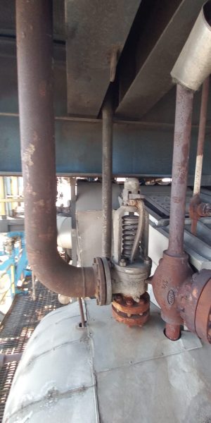
Proper valve selection for boiler safety
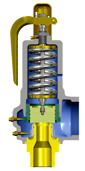
All boilers must be protected by pressure relief valves that are correctly specified and sized to meet the requirements of ASME Code Section I, ensuring they operate perfectly when necessary. While valves built in accordance with ASME Section VIII are also designed to relieve excess pressure, they do not provide relief at an overpressure of just 3%, which is a mandatory requirement for boiler protection under ASME Section I. Pressure relief valves that protect boilers, as per ASME Section I, have more complex engineering to achieve their flow capacity with just 3% overpressure. They also have a narrower opening pressure tolerance compared to valves designed in accordance with ASME Section VIII. Furthermore, the materials used in the construction of internal components undergo a more rigorous selection process in valves that protect boilers. For other components, such as the body and bonnet, the materials are essentially the same in both valve designs and must comply with paragraph PG-73.3.3 in ASME Section I (2023 edition) and 3.3.1 in ASME Section XIII (2023 edition). In both cases, reference is made back to ASME Section II for the actual materials to be applied.
In conclusion, it is crucial to ensure that the appropriate pressure relief valves, designed and certified to meet the specific requirements of ASME Code Section I, are installed on boilers to guarantee their safe operation and protect personnel and equipment from potential hazards associated with excessive pressure.
About the author
 Todd Loudin is Director of Mining and Metals North America, Valmet Flow Control business line, located in Linthicum, Maryland. Loudin has over 30 years of experience working with industrial valves and pumps, mostly with Flowrox pinch and knife gate valves and pumps but several years also Neles valves. He has Bachelor of Science in marketing and executive MBA from Loyola College, Baltimore. He can be contacted at With extensive experience in the field, Artur provides training and technical courses to share his knowledge and expertise with others in the industry. He is also the author of the book “Válvulas: Industriais, Segurança e Controle” (Valves: Industrial, Safety, and Control), which serves as a valuable resource for professionals working with valves in various applications.
About this Technical Story
This Technical Story is an article from our Valve World Magazine, August 2024 issue. To read other featured stories and many more articles, subscribe to our print magazine. Available in both print and digital formats. DIGITAL MAGAZINE SUBSCRIPTIONS ARE NOW FREE.
“Every week we share a new Technical Story with our Valve World community. Join us and let’s share your Technical Story on Valve World online and in print.”
