


Size the bypass globe valve to have the same minimum required Cv as its control valve.
By Ron Merrick and Ashley Casteel, Fluor
During the 19th and early 20th centuries, many different valve designs were invented – some more successful than others. Eventually, these designs coalesced into three broad categories: cast in iron and later steel, which corresponded to the three main fluid control methods of shutoff, throttling, and non-return. These three types of valve, the gate, globe and check, even had their own abbreviation – GG&C, which at one time was almost synonymous with the term ‘valves,’ since they were the overwhelming majority of valves in use.
National standards bodies and engineering societies recognized that disasters were occurring which could have been prevented through standardization. In the USA, the American Society of Mechanical Engineers (ASME, founded 1880) first worked on boiler safety to reduce the number of explosions. In the piping arena, they worked on standardizing bolts and screw threads, pipe sizes and flanges, with a valve general design standard (B16e of 1949, later B16.34 of 1977) being an outgrowth of the flange standard.
The American Petroleum Institute (API, founded 1919) worked on standards for hydrocarbon valves starting with the most common gate valve (API 600, first published 1949). Later, they issued standards about smaller gate valves (API 602, 1962) and double-door check valves (API 594, 1974) but through the 1990s, there was very little interest in creating a standard specifically for globe valves.
One possible reason for the lack of interest in an API globe valve standard was the steady reduction in the use of hand-operated globe valves as a means of controlling the operations of a process unit. The growth of control systems and remote operation of valves, first pneumatic and later electronic, meant that by 2010, one large international engineering company found that only 9% of their worldwide valve purchases were globe valves.
How we found the problem
Opportunities, it is said, often arise from a problem. In 2007, my colleagues were part of a task force designing and building a new crude unit at a major US refinery site. The owner expected a significant tax credit if the unit could be started before the end of the year, and commissioning of the unit was under way. During the week before Christmas, we started getting reports from the site that the bypasses around control valves were leaking from the stem and packing area, and were having flash fires.
Since the unit wasn’t completely mechanically complete, some control valves were not yet in place or were still being configured, so the unit was “running on bypass,” with operations personnel manually adjusting the bypass globe valves as the unit was being brought up to full operations. As this was part of a major expansion, many of the operators were newly hired. The process temperatures were already high enough to be above flash point, so any leakage immediately broke out into small fires, which naturally caused the operators to close the valves and back away, and the startup was in serious jeopardy.
When new valves have a problem, the first course of action is generally to assume the product is defective. In this case, the valves were provided by an approved manufacturer with a very high-quality reputation, reinforced by the fact that no other valves from this manufacturer were reported to be leaking. We started to suspect another issue when we figured out that all these valves were in locations where flashing (a sudden release of vapor from a hydrocarbon liquid when the pressure drops) was expected.

We theorized that the flashing was occurring inside the valve, and the vibrations and pressure fluctuations were causing the leakage. The operators said that they were only opening the valves about one or two turns when they saw and heard the leakage from the gland and, in some cases, saw fire. We realized that the small partial opening was causing a large pressure drop and thus was instigating flashing.
Because we were in a time bind trying to bring the unit completely online, we decided to cut into the bypass line at each of the affected control stations and add a second globe valve, in order to split the pressure drop across two valves. This worked, we were able to successfully complete the startup and the client was happy. We checked with several of our major clients and most agreed that they had seen similar problems, but didn’t have much insight into the reasons beyond “a lot of globe valves do that.”
A number of operators said it was common to hear globe valves making those vibrating noises, but most didn’t have an opinion on exactly what caused this. One major refining company had actually studied the problem and issued a practice limiting the allowable pressure drop across globe valves.
The normal practice in our office and many others was to arbitrarily size the bypass line in a control station as the next line size down from the pipe size in and out of the control station. We even published a chart showing how to do that. For example, if the line in and out of the control station was NPS 6 (DN 150), the pipe size for the bypass was selected as NPS 4 (DN 100).
This mirrored the control valve sizing in broad terms, in that a control valve with port size of NPS 4 was usually selected as a consequence of the control valve being sized with a specific minimum Cv based on the desired pressure drop and flowrate. Note that port size only broadly follows the choice of specified control valve Cv.
This sizing method often resulted in the globe bypass valve still having quite a bit more Cv than the control valve actually had, and as a consequence the globe bypass was simply unable to be throttled down to a desired flowrate, especially on startup situations. From this, we developed our own corporate practice on the necessity for reviewing control station design in lines with flashing service. Essentially, it requires the globe valve bypass to be specified with a flow coefficient Cv at least equal to that specified for the actual control valve.
In practice, that means in the case of the process line being NPS 6, the globe bypass valve would often be sized at NPS 3 or 2 (DN 80 or 50). A year or two after our initial startup problems, we applied that practice to a similar crude unit being built at another refiner’s largest refinery, with a similar number of flashing services, and brought the unit up with no valve fires and no undue control valve bypass issues.
A new standard
The American Petroleum Institute holds regular meetings on standards for refinery valves and, during these sessions, the representatives of operating companies share their engineering experiences and concerns with each other. The issue of vibrating and leaking globe valves came up, and the end-user committee proposed that a new standard be created specifically for refinery globe valves, to require design features intended to reduce or eliminate the problems.
API’s method of creating a new standard is to appoint an engineering specialist from a member refining company, who issues a call for volunteers from engineers drawn from valve manufacturers, engineering contractor representatives, and of course from the operating companies themselves. The purpose of this diversity of interests is to balance needs and desires from the user community with the practicality of design and manufacturing.
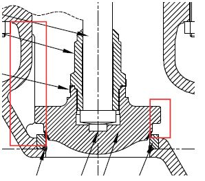
The starting point for developing this new spec was incorporating the structure of API 600 with the technical information contained in BS 1873, the most widely used existing specification for process globe valves and the most comparable international valve standard. One issue the task group faced was the forces and loads in operation of globe valves, which are quite different than gate valve operation. There is a significant upward force on the stem during operation, leading to possible buckling failure (column loading). Analysis of this problem, using 13 chrome (410 stainless or F6) stem material as the strength basis showed that a number of size and rating combinations, mostly in larger sizes and higher ratings, needed a larger stem diameter than previously specified.
Practices in design of globe valves for other industries were also considered. High-pressure globe valves for the power industry, which have for generations EMISSION CONTROL been used as block valves as well as for throttling, were considered. These valves have guide ribs extending the full distance of the disc’s travel. Similar practices of guiding the disc are used in many control valves. The committee decided to mandate this design for higher pressure globe valves, in Class 900 and higher. Other design requirements were built into the standard, such as the means of handwheel attachment to the stem and the degree of allowed wear in the stem travel.
The standard was released as API 623, First Edition, in September 2013. API’s practice is to allow a grace period of six months before the provisions of a new standard become mandatory, as shown on the cover page of API standards. As this was a new standard, it was anticipated that some time would elapse before manufacturers became fully capable of meeting the design requirements, and more importantly, some time would elapse before end-users and contractors could modify their ordering systems to incorporate the changes.
During the first year after issue, we watched as numerous manufacturers began to release customer notices of the upcoming design changes. As an engineering contractor, we were successfully able to procure valves to the new design after the allotted time for implementation. And, to the best of our knowledge, the issue of flashing hydrocarbons and excessive vibration has not been reported again. Due to the success of this design, and the desire for continuous improvement, the second edition of API 623 in its scheduled five-year update cycle has expanded the requirement for fully body-guided discs to all ratings of globe valve.

One last valve story
During the crisis of December 2007 referred to above, we frequently heard that the valves “were breaking.” That’s a common turn of phrase to express what happens when something performs in an unexpectedly bad way, but it wasn’t literally true, in that with some packing adjustments and more careful operation and the piping modifications we performed, those same valves continued to operate.
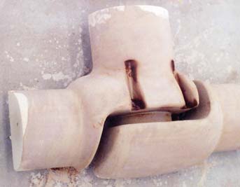
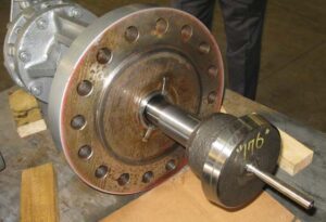
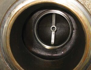
However, later, one of the user members of the API 623 task group brought in a photo of a globe valve that had literally broken under the stress of vibration. The stem of this valve had actually fractured from the vibration, so the disc and a short section of the stem had separated from the body of the valve. So, yes, at least one globe valve had actually broken from the high vibration caused by throttling.
About the authors
 Ron Merrick, PE is recently retired after a forty-five-year career in specifying valves and other piping materials. He retired as a Senior Fellow and Director of Piping Material Engineering at Fluor Enterprises in Sugar Land, Texas, supporting the worldwide piping description and specification catalog.
 Ashley Casteel, PE is a Piping Material Engineer at Fluor Enterprises in Sugar Land, Texas with project experiences covering chemical, refining, and nuclear projects. Her professional involvement includes membership in API Refining SCOPV Division, and memberships on ASME B16 Subcommittee C, F, and N.
About this Featured Story
This Featured Story is an article from our Valve World Magazine, June 2023 issue. To read other featured stories and many more articles, subscribe to our print magazine. Available in both print and digital formats. DIGITAL MAGAZINE SUBSCRIPTIONS ARE NOW FREE.
“Every week we share a new Featured Story with our Valve World community. Join us and let’s share your Featured Story on Valve World online and in print.”