

Over the course of 30 years, SAF ™ 2507 (UNS: S32750) super-duplex stainless steel has advanced the industry by allowing a lighter, stronger, and more cost-efficient alternative to higher nickel alloys for valves, fittings, flanges, and other critical components.
By Dr Munir Al-Saadi, Magnus Brink, and Marcus Hillbom, Alleima
With its austenitic-ferritic (50/50) microstructure, super-duplex has twice the strength of conventional austenitic steels, while providing excellent crevice and pitting resistance. To ensure these properties were met, UNS, ASTM, API, NORSOK, and other regulatory bodies set stringent tests for corrosion, porosity, hardness, and more. However, the hot-work reduction ratio was not specified, nor could it be measured.
In recent years, customers have increasingly specified a hot-forged reduction ratio of around 4:1 for wrought super-duplex. This appears to be a carry-over practice from producing forged austenitic and higher nickel alloy grades, where a higher reduction ratio minimises the risk of porosity and degradation. However, unlike austenitic and higher nickel alloys, duplexes already have low porosity due to ferritic phase solidification and tight core. Recent research by Alleima shows that super-duplex maintains consistent quality and meets all acceptance criteria in a hot-worked condition down to 2.5:1. In other words, the 4:1 ratio is not only an overcompensation – but is also irrelevant.
Full-scale production study
Carried out in Sandviken, Sweden, Alleima explored the influence of forge reduction ratios on mechanical properties and corrosion resistance between 1.5:1 and 6.0:1 through a thermomechanical process to a final billet dimension and quench annealing.
The aim was to determine if it was necessary to manufacture 25Cr duplex with a minimum total hot-work reduction ratio of at least 4.0:1. Proving that this was not the case would generate several advantages for customers. These include the flexibility to order wider diameters with 2.5:1 reduction, faster delivery due to the wider availability of materials, and more sustainable and energy-efficient manufacturing through shorter production times.
Production route and reductions
The production route was a basic thermomechanical processing cycle with solution annealing. The heating or reheating temperature was the same for all billets. Each workpiece was subjected to hot forging with a total reduction ratio to obtain a square billet, followed by water quenching. The total hot-forging reduction ratios (RR) were 1.5, 2.0, 2.5, 3.0, 3.5, 4.0, 5.0, and 6.0, which are equivalent to relative deformations of 34%, 50%, 60%, 67%, 71%, 75%, 80%, and 84% respectively.
Eight blooms, one batch, same heat
Eight blooms measuring 365 x 265 mm and produced in a continuous cast from the same heat were analysed. The chemical composition was based on UNS S32750 in accordance with ASTM A479-14. The mechanical properties were evaluated at several alternative forging reduction ratios ranging from 1.5:1 to 6.0:1.
Samples were cut from a close to mid-radial position (1/4 thickness) and assessed at least three times. Structural investigations were conducted using Light Optical Microscopy (LOM).
Testing protocols
A fully-instrumented 750 J Charpy impact tester was used on standard Charpy V-notch specimens in both longitudinal and transverse directions, managed at -46°C. Longitudinal and traverse tensile tests for fracture, rigidity, and other mechanical properties were undertaken at room temperature (RT).
HRC hardness with transverse direction tests were run at RT. Samples were cut out transversely to the direction of sample forging. Pitting corrosion testing was conducted according to ASTM G48 Method A. Micro-structural observations were performed using scanning electron microscopy equipped with an electron backscatter diffraction (EBSD) analyser incorporating an orientation imaging microscopy (OIM) system. The ferrite fraction was determined by electron diffraction backscattered analysis. The mean austenite/ferrite grain size was evaluated by the line intercept method counting at least 2000-3000 grains on at least three typical EBSD scans.
The microstructures were examined using LOM magnified to 400x. The samples were electrolytically etched in a 10% oxalic acid solution to reveal Cr2N and in 40% NaOH at 2.5 V, 3-10 sec, at RT to reveal sigma phases. The procedures were listed in ASTM E 407. Metallographically prepared longitudinal/transverse sections of broken tensile/notch impact specimens were etched in 40% NaOH at 2.5 V, 3-10 sec, at RT to reveal the prior austenite/ferrite grains’ boundaries.
Test results
The cast structure was nearly broken down in workpieces forged using total reductions: 1.5:1 and 2.0:1. However, large columnar grains were still visible. This was not the case for total reductions above 2.0:1 where the cast structure was totally broken down. Very small differences in structural breakdown were seen in forge reductions above 2.0:1.
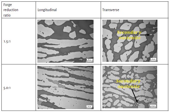
LOM images for a total reduction ratio of 1.5:1 and 5.0:1 on etched specimens showed free from intermetallic precipitates, sigma phase and discrete/ stand-alone nitride precipitates, Cr2N. The shape of austenite in the longitudinal direction was smaller/ thinner with more straight boundaries and elongated relative to the transverse specimens (Figure 1). Round austenite grain structures were observed with all forging reductions.
However, they were small, isolated lakes of equiaxed coarse grains dispersed through a ferrite-grained matrix. The ferrite area occupied by the coarse austenite grains appeared in irregular fractions for the forge reductions. For the reduction of 1.5:1 at the transverse direction, equiaxed austenite grains were observed, which mostly nucleated at the ferrite-ferrite grain boundaries. The forging of super duplex SAF™ 2507 formed a fine elongated grain structure of austenite and ferrite along the forging direction.
Ferrite content measurement
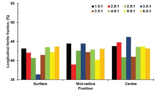
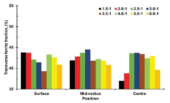
The changes in the longitudinal/transverse ferrite content with investigated sample position, surface, mid-radius, and center of a total deformation level are given in Figures 2 and 3. The average ferrite fraction measured by electron diffraction backscattered analysis for the different deformation levels produced by the forging process is within 35-55% in solution-annealed base material.
Mechanical properties of as-quenched
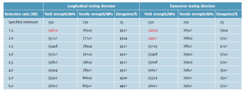
Elongation average values for both the longitudinal and transverse at each level of deformation ratio are given in Table 1. The room temperature mechanical properties at the transverse section showed 0.7 to 0.8% lower elongation (ductility) values compared to longitudinal specimens.
The mean values for longitudinal and transverse strength at each level of deformation ratio are shown in Table 1. The red colour indicates the transverse and longitudinal yield strength of specimens (RR=1.5:1 and 2.0:1) that did not satisfy the acceptance criteria requirement. Otherwise, no significant differences in yield and tensile strength were obtained for separate forging schedules at the same total reduction. The yield strength above 550 MPa and ultimate tensile strength above 750 MPa with lower scatter was obtained in between RR= 2.5 and RR= 6.0 after hot-forging followed by quench-annealing.
Charpy V-notch impact toughness test
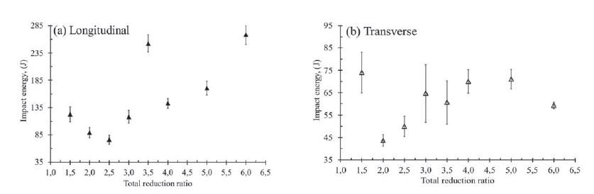
Notch impact values for both longitudinal and transverse specimens at each level of deformation ratio are provided in Figure 4 (a-b). Impact energy in the longitudinal direction as a function of the total forge reduction ratio for the specimens in the quench-annealed condition is shown in Figure 4a.
The longitudinal single and average impact energy above 35 J and 45 J respectively with low scatter were obtained for all reduction ratios.
The transverse single/average impact energy above 35/45J with high scatter was acquired between RR= 2.5 and RR= 6.0 after hot forging followed by annealing. A common design criterion for NORSOK standards is that the impact energy obtained in Charpy-V specimens should be higher than 35 J single and 45 J average at a temperature of -46°C (-51°F) in wrought bar products. The red triangle in Figure 4b indicates the transverse average impact energy level of specimens (RR= 2.0:1) that did not meet the desired NORSOK requirement of 45 J average.
Hardness HRC test
Transverse hardness tests with total reduction ratios at the mid-radius position were performed using the Rockwell scale C according to the EN ISO 15156-3:2019 standard. The transverse hardness value of a minimum of 18.5 HRC and a maximum of 23.5 HRC with low scatter was achieved for detached total reduction ratio after forging followed by quench annealing.
Pitting corrosion resistance
A ferric chloride corrosion test in accordance with ASTM G 48, Method A was performed. The test temperature and duration of the test were 50°C (122°F) for 24 hours. The transverse test specimens were taken from the surface to center position. No more than 0.24±0.05 g/m2 of weight loss was detected for all single reductions in the solution annealed-condition. No pitting at 20 x magnification was observed.
Advancing together
Virtually no influence on reduction ratios was found from 1.5:1 to 6.0:1 on the materials properties of the forged super duplex and the research cites the following highlights:
- No porosities were observed on the macro-etched continuous cast material and a higher total reduction of 2.0:1 has a major influence on structure breakdown.
- A higher forging reduction led to slightly higher yield strength after quench-annealing. However, no significant differences in the mechanical properties were detected.
- The highest as-quench annealed yield strength measured in the longitudinal and transverse directions was 566 MPa/560 MPa, respectively. The highest ultimate tensile strength was 805 MPa/795 MPa respectively, both of which occurred in the sample forged to the largest total reduction ratio. All samples showed good ductility (above 35%). Above 2.5:1 forge reduction subsequent annealed sample met relevant industry standards.
- For all total reduction ratios, the microstructure after solution annealing showed no harmful phases. The ferrite fraction percentage for all tested specimens was between 35% and 55%.
- No significant differences were found between the HRC hardness values of the reduction ratios. These values are between 18.5 HRC and 23.5 HRC and are lower than the material property requirements (28 HRC). For all conditions, the studied samples exhibited a weight loss of less than 0.24 g/m2 evaluated according to the ASTM A48-A standard.
The Alleima research challenges the status quo. Customers can order larger diameters and get their orders faster and support a more efficient and sustainable production process using less energy. The research advances efforts toward a more sustainable future as the material is made from 84% recycled steel and produced using 100% fossil-free energy.