Derek’s flash of inspiration for his innovative valve design came during his time at BP.
He had been handed responsibility for all the so-called “sandy” technology and got talking to the experts running a flow loop.
This was designed to pump assorted slurries through valves as a way of testing their ability to continue to seal under abrasive conditions.
However, Derek’s professional interests also extended to testing and calibrating sand detectors.
For that purpose he had a cylinder rated to 5,000 psig which he wanted to be able to use to inject calibrated amounts of sand slurry into any well.
The problem was that although most wells flow at a much lower pressure that 5,000 psig, the shut-in pressures on some high-pressure wells can exceed this rating.
This led Derek to consider making a valve that would automatically isolate the cylinder if somebody were to shut-in a flowing well.
His rough sketches caught the eye of several colleagues who all commented that his design could make a very useful valve indeed.
They encouraged him to take his concept further but the sheer pressure of working in the oil industry meant Derek had to shelve his plans.
Positive feedback
Later on, having taken early retirement from BP to set up his own consultancy company, Derek had more time to devote to his valve design project.
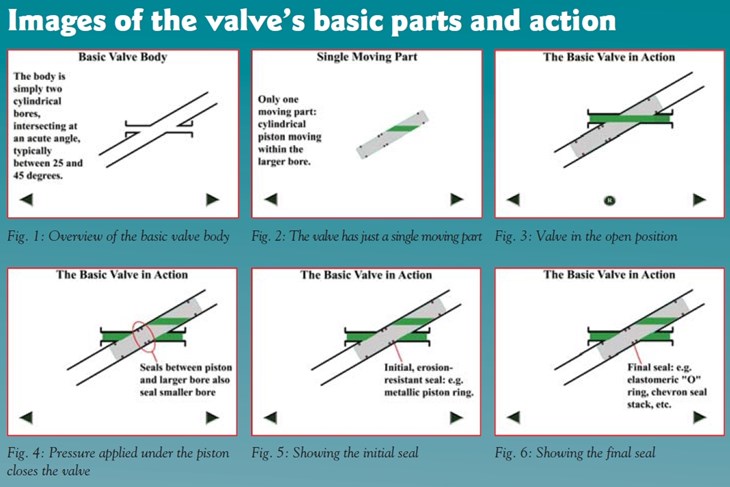
Derek therefore made a working demonstration model using transparent Perspex to better show the internal working.
Despite plenty of positive feedback, though, sadly no manufacturers have as yet shown a concrete interest in licensing the idea.
Comments Derek: “the valve industry tends to be conservative, especially with designs that already have customer approvals and for which they are already tooled-up. So companies are naturally reluctant to invest time and energy in tooling up for a completely different design that might not sell.”
Derek believes that is a missed opportunity for the industry as a whole.
“I believe it could be easier to manufacture and more reliable than existing full-bore designs, with no possibility of stem seal leakage and no need for a separate actuator.”
HIPPS
A main use for the valve could be in HIPPS: High Integrity Pipeline Protection Systems.
Says Derek: “pipelines from platforms to shore are often rated for a (flowing) pressure significantly lower than the shut-in pressures of the wells. This is done to save significant cost. This is fine if the wells are shut-in at the wellheads, but if the line becomes plugged or is shut-in at shore, the pressure could rise enough to burst the line.”
He further explained that most HIPPS systems have electronic pressure gauges feeding into a computer system that operates a valve hydraulically or electrically at the inlet of the line. In other words, at the “pressure break” between the high and low pressure systems.
Derek: “to ensure integrity there tends to be a lot of duplication and a back-up power supply.”
“By contrast, my design is purely mechanical and much less complicated. It could also be very useful though in other areas, such as to protect the platform pipework, the separators, etc.”
Derek’s motive for sharing his design has nothing to do with seeking financial gain. “I’m an engineer and I have an idea for a valve design that I really believe could help the industry.”
“For that reason alone I would like to share my drawings with a partner who can turn them into physical, viable products.”
“Therefore if any valve makers are interested I’d really like them to contact me.”

Derek has prepared some videos and animations which clearly demonstrate the working features of his valve design. Unfortunately it was not possible to include these videos before this web-article was uploaded. Valve World will do our best to have these videos included as soon as possible. However, a copy of the valve animation file can be found on YouTube at:
https://youtu.be/Y6yX9C6hYds


