Flame arresters and breather valves are widely used in the industry and are required to always be fully operational. Proper maintenance is of great importance, as the consequences of any failure can be devastating. Martin Hundt explains how intelligent measurement technology can make a difference.
By Martin Hundt, KITO Armaturen GmbH
Flame arresters and breather valves are used in various applications in the industry, such as in storage tank farms, processing systems, vapor combusting systems, flare, and incineration systems, in loading and unloading processes in logistics, in vapor recovery units or as integrated components of equipment.
All these industries now benefit from digitisation and Industry 4.0, which is finding its way into the field of safety devices. Flame arresters and breather valves safeguard the mentioned systems and, owing to continuous usage and the demand for uninterrupted availability, must always remain fully functional at 100%. The failure of a device can have devastating consequences. Generally, maintenance intervals for devices should be established based on the operator’s operational experience.
According to the German Industrial Safety Ordinance (BetrSiVO) under §15, protective systems such as flame arresters or venting valves with integrated flame arresters must undergo an inspection by the approved inspection agency prior to start-up and before re-commissioning after mandatory changes. This includes a risk assessment according to §3, section 6 of the German Industrial Safety Ordinance (BetrSiVO), where the employer is responsible for determining the type, scope, and deadlines for the required inspections. For new installations, it is advisable to allocate a conservative time period, which depends on various factures such as:
- The design of the device
- The construction material in terms of potential corrosion and fouling
- The operating pressure and temperature
- The fluid that may contain contaminants or solid particles, polymerise, or be viscous
- The cyclic, static, or changing operating conditions within the plant
For recurring inspections according to §16 of the German Industrial Safety Ordinance, the recommended manufacturer’s instructions should be followed. These intervals can be extended if an effective maintenance concept according to German Industrial Safety Ordinance §16, Number 4.1 has been formulated in consultation with the approved inspection agency. This can change the prescribed recurring inspections from 3 to 6 years.
These defined maintenance intervals must be adhered to and documented. They can be adjusted, shortened, or extended based on the operator’s experience in consultation with the qualified person, who possesses specialised knowledge in explosion protection, or the approved inspection agency. Despite all these recommendations, there are no calculation models or standards available to calculate and/or ensure the functionality of the valves. In order to optimise this iterative process, digitalisation is now being employed. Additionally, digitalisation can assist operators, particularly those with limited operational experience, in their decision-making process for defining maintenance intervals. These intervals are often estimated very conservatively, which can significantly reduce plant availability.
The further development of digitisation can now compensate for a lack of operating experience as well as the challenge of the various applications and operating conditions within an existing system. Thanks to the implementation of intelligent measuring technology, operators are now able to monitor the real-time operating status of the safety devices, access device statuses, and proactively schedule preventive maintenance or repair work in advance. This not only prevents devices failures but also ensures maximum system availability, allowing for optimal scheduling of maintenance work.
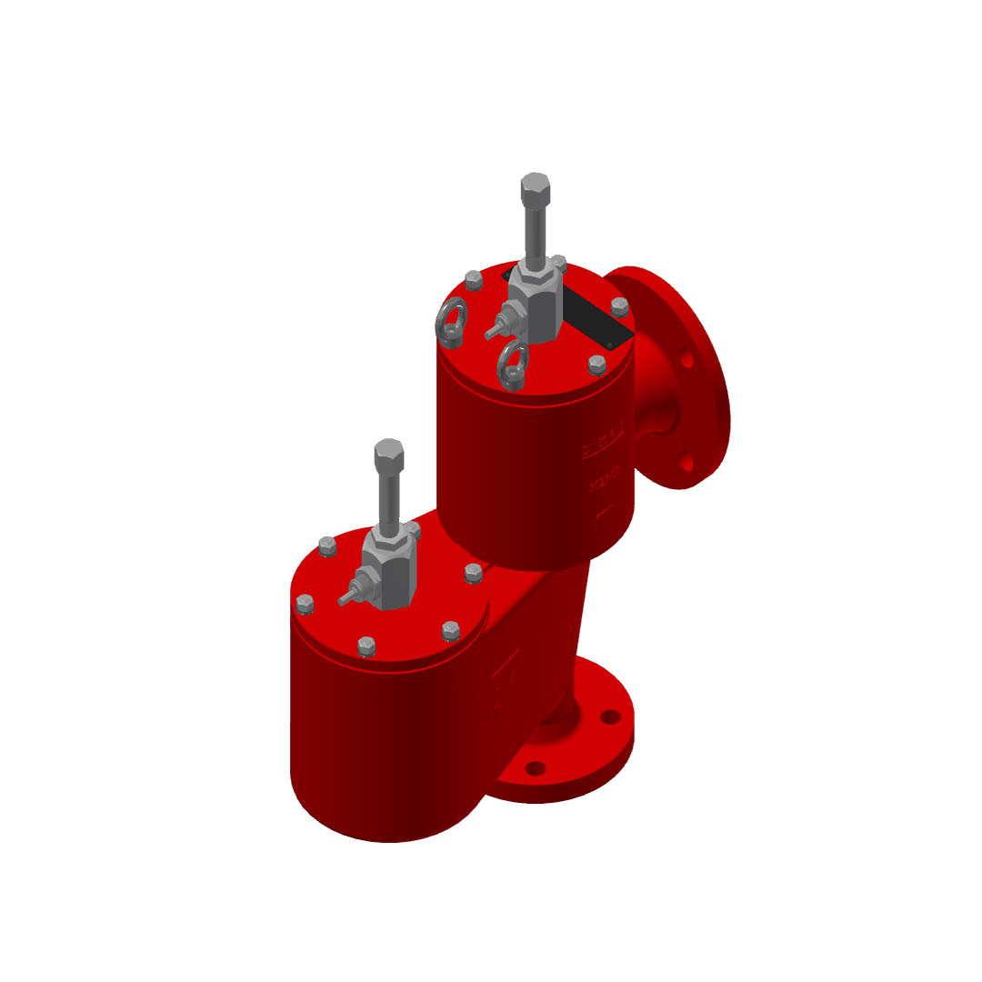
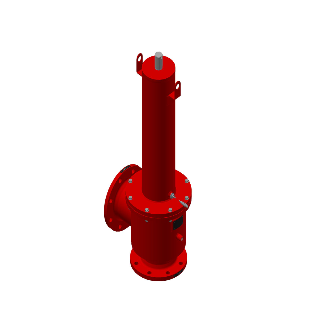
The challenge of monitoring breathing valves
Breathing valves can experience failure due to various factors, such as mechanical issues with individual components, leaky and destroyed valve disks, and valve seats getting damaged from chattering. Valve chattering describes the rapid, repetitive opening and closing of a breather valve. It occurs when a valve disk oscillates between its open and closed positions due to fluctuating fluid pressure or flow conditions in the system. Proper breather valve design, sizing, and control are crucial in preventing valve chatter and ensuring smooth and reliable operation of the system.
Another cause could be a valve getting stuck in the open position due to pressure surges or improper commissioning, where transport locks have not been removed. Additionally, heavy contamination can hinder proper valve closure. The presence of polymerising substances in the application can lead to deposit formation or sticking on the valve disk. This, in turn, may increase the set pressure for weight-loaded valves and delay the opening, posing a threat to the system’s safety.
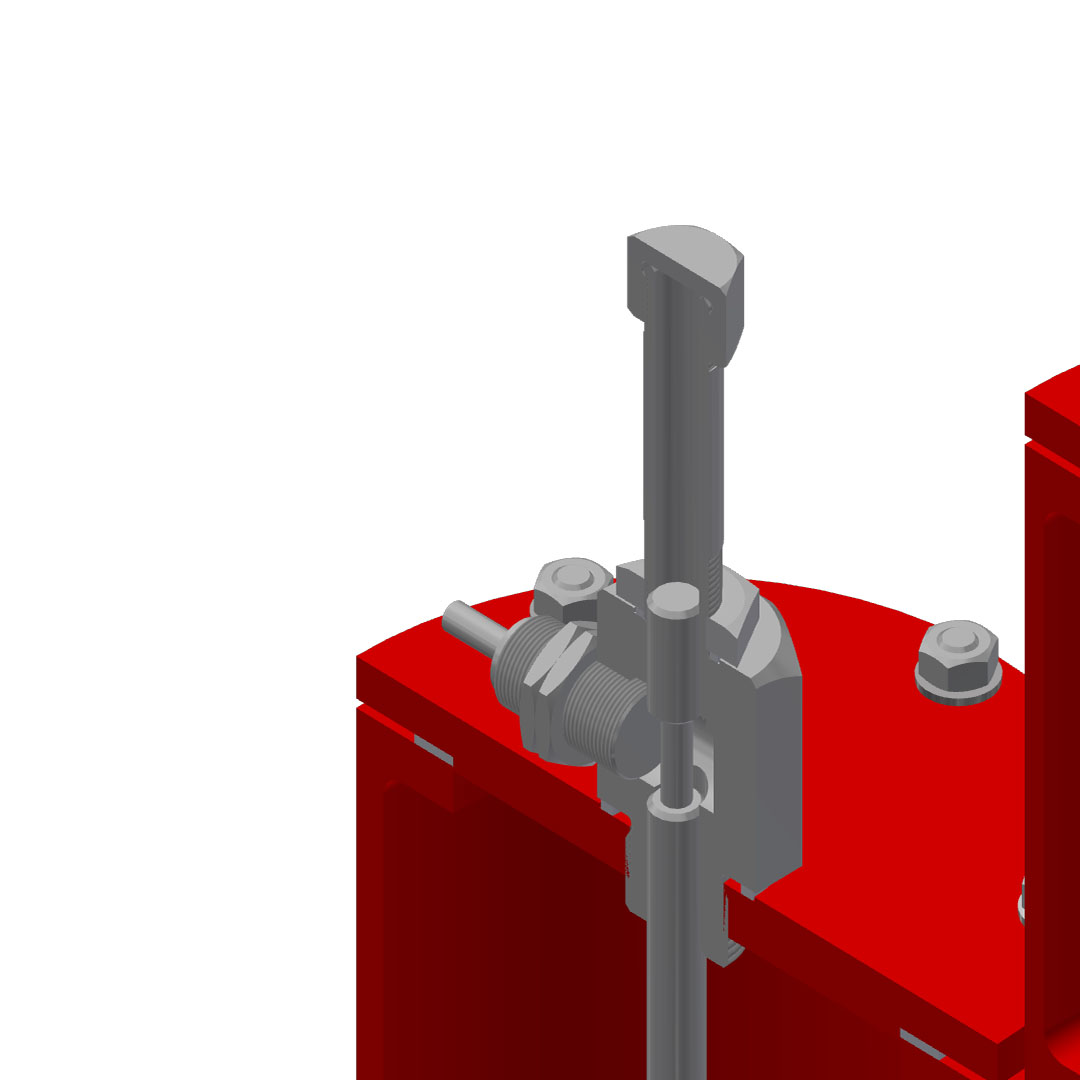
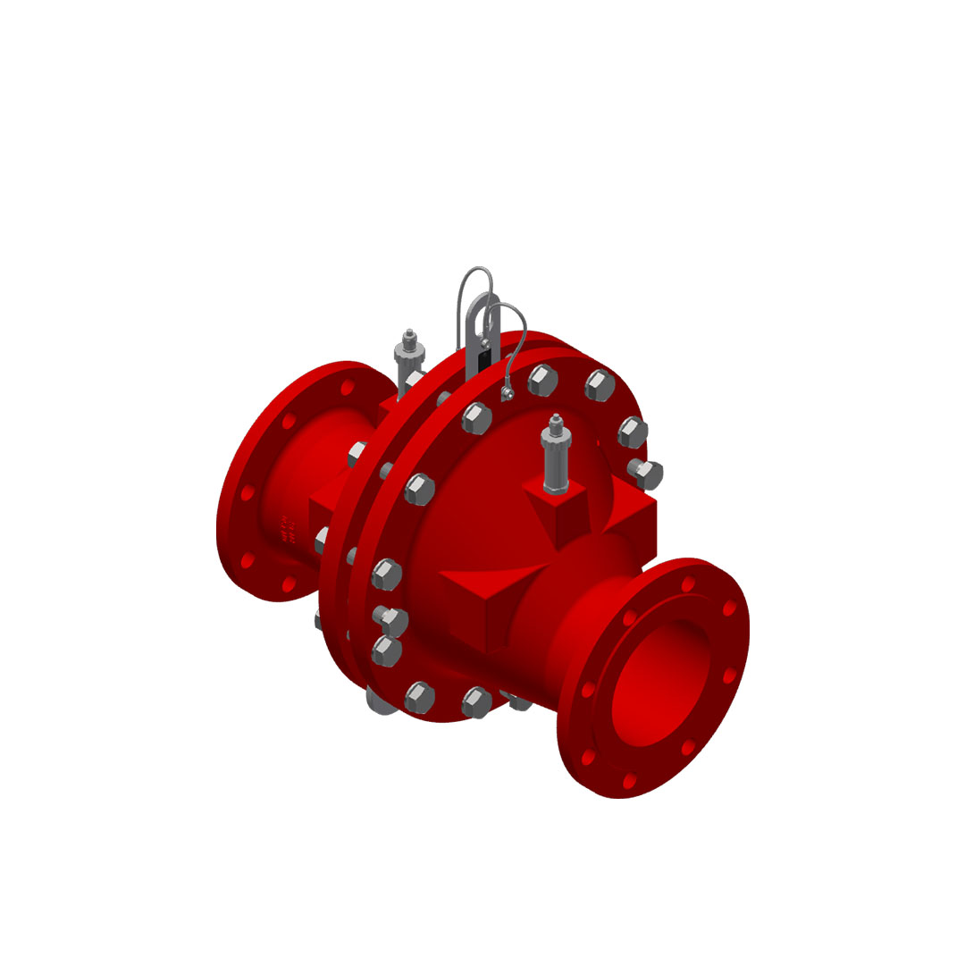
To counteract these challenges, we recommend the use of proximity switches for valves. These systems enable real-time monitoring of the valve’s status during operation, providing valuable insights into their performance and conditions.
In general, each valve requires an increase in pressure above the set pressure to achieve full opening, with the valve disk always guided during the process. As the valve opens, the valve disk and valve spindle move upwards. Once the highest point of the spindle reaches the position monitoring system (located outside the valve body in the case of weight-loaded valves), the proximity switch emits a signal indicating that the valve has opened and is now in the open position.
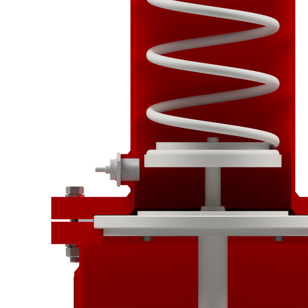
If the pressure drops, the valve closes again when the closing pressure is reached. The valve disk descend onto the valve seat and the valve spindle moves away from the proximity switch, and again, the signal is emitted that the valve is now closed. These proximity switches are used with both weight and spring-loaded valves and can also be used in ATEX zones. The difference in position monitoring between weight-loaded and spring-loaded valves lies in the placement of the proximity switch. In case of the spring-loaded valve, the proximity switch is not mounted on top of the spindle; instead, it is positioned at the lowest point of the spring inside the spring housing.
The challenge of monitoring flame arresters
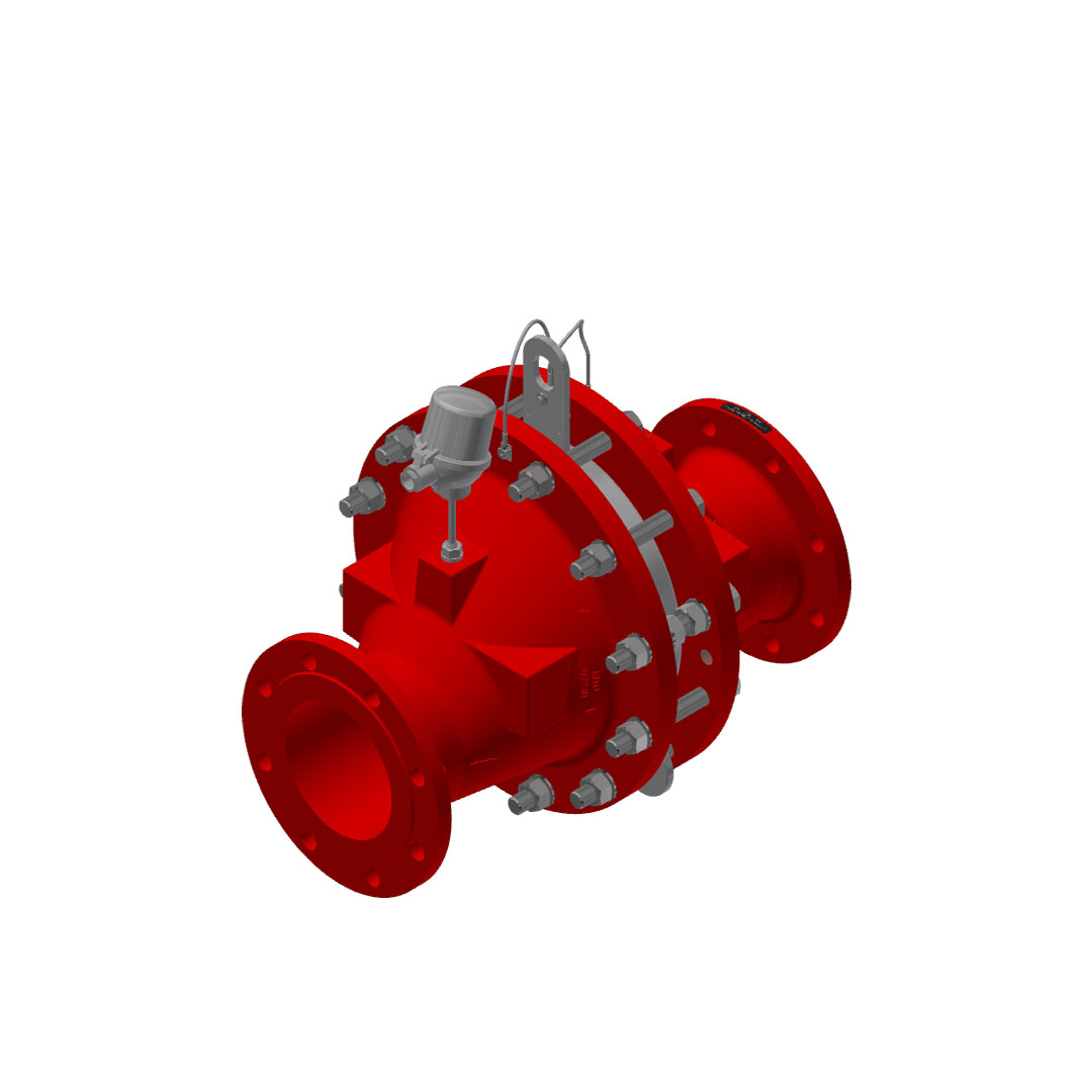
Contamination and subsequent clogging of the flame arrester is a potential cause of failure, leading to an increase in pressure drop. To obtain real-time information on the degree of clogging inside the flame arrester, we recommend utilising a differential pressure measurement system. The pressure transducers are mounted on both sides of each half of the device, both before and after the actual flame arrestor unit.
Upon installation, the pressure loss is measured under clean conditions. Subsequently, if the pressure loss increases due to clogging, the differential pressure measurement will detect and record the rise in pressure drop. A maximum pressure drop must be defined by the operator. Once this limit is reached, the flame arrester should be cleaned to ensure proper functionality and safety. Another danger arises from the possibility of short time (stabilised burning for a specific period of time) or endurance burning (stabilised burning for an unlimited period of time) that can occur in certain systems (e.g., vapor combusting systems, flare and incineration systems and burners).
Regular approvals in the area of deflagration for in-line deflagration- and detonation arresters of type 4 (according to EN ISO 16852) are covering stabilised burning for a short time period (called burn time) of one minute. If this burn time is exceeded, the flame arrester can no longer provide protection. The heat input into the flame arrester becomes too high, causing it to heat up and reach the auto-ignition temperature of the substance on the protected side of the device (the side where the system to be protected is located). This leads to the mixture igniting by itself without any external ignition spark.
If, during the safety assessment, it is determined that short time burning with a burn time exceeding one minute or an endurance burning may occur, temperature sensors must be employed to detect potential fires. The temperature sensor should be installed on the unprotected side of the device, where the flame is suspected to emerge or where the ignition source is present. In addition, a name plate is essential to ensure that the flame arrester is installed correctly in the pipeline. This prevents the possibility of installing it the wrong way around, which could lead to the temperature sensor being accidentally placed on the protected side. Such an error would result in delayed flame detection, potentially exceeding the allowed burn time and causing the flame arrester to fail. Bidirectional flame arresters cannot be used symmetrically for any longer in case the short time burning only functions from one direction or is actively monitored with a temperature sensor when a corresponding risk assessment requires it.
A second factor to consider is the response time of the temperature sensor. The temperature sensor(s) must be integrated into the process control system of the plant so that when the sensor detects a critical temperature rise, countermeasures can be automatically initiated. According to the standard, the temperature sensor has a window of 0,5 x burn time of the device, 30 seconds in this case, to emit a signal. However, in practice, the signal is often emitted much faster than this timeframe.
Countermeasures must be taken automatically within the remaining burn time, at latest when the burn time ends, such as shutting off the fuel supply, inerting with air, steam, nitrogen, or other substances, or rerouting the stream as well as shutting off the pipeline completely. In demanding applications, intelligent measurement technology for safety devices can not only minimise maintenance intervals, maximise system availability but also prevent unplanned downtimes. This enables operators to plan maintenance work over long term and carry it out cost-effectively.
About the author
 Martin has almost 15 years of experience in the chemical, petrochemical, pharmaceutical and food industries. His focus lies in safety valves: design, installation and operation, which is all very hands-on. Within the framework of Huckauf Ingenieure GmbH’s academy, he acts as a speaker and moderator on a wide range of topics. His main aim is to impart specialist knowledge and content to the participants.
For more information, please visit www.kito.de
About this Featured Story
This Featured Story is an article from our Valve World Magazine, August 2023 issue. To read other featured stories and many more articles, subscribe to our print magazine. Available in both print and digital formats. DIGITAL MAGAZINE SUBSCRIPTIONS ARE NOW FREE.
“Every week we share a new Featured Story with our Valve World community. Join us and let’s share your Featured Story on Valve World online and in print.”


