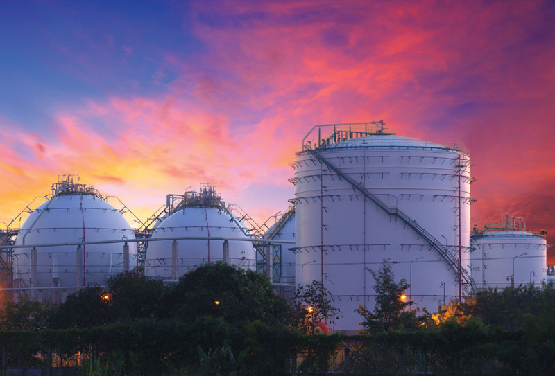
Breather valves are designed to regulate tank pressures to protect the integrity of the tank construction, minimize product loss and to protect the environment and ensure worker safety. Designing and selecting the appropriate breather valves entails various steps (size, material selection etc.).
In the selection process, various requirements come into play such as the process configuration, pressure levels or external thermal influences.
By Martin Hundt
Conventional storage tanks look very robust, but in relation to their volume they are actually not much thicker than a beverage can. Because of this, they are very vulnerable to the occurrence of pressure differentials and vacuum. They can be damaged even if the maximum allowable tank pressure is exceeded only slightly and for a short time.
For this reason, it must be ensured that the resulting/occurring pressures never exceed the maximum allowable tank pressure levels. If the tanks were permanently atmospherically aerated and vented, emissions would arise. Emissions are basically caused by work losses (displacement of gas from the gas space during filling or empty-ing processes), by standstill (weather-related breathing capacities with changes in pressure and temperature), by operating losses (leaks at flange connections, valves or seals of pumps) and by cleaning processes and revisions.
First step
To meet the requirements of the anti-pollution law (i.e. BImSchG, VDI 3479:2010), so-called breathing valves are used. These valves ensure that, in the event of critical overpressure or vacuum, the tank is aerated or vented by the adequate amount. At the same time, the tank should be closed and sealed if no critical process conditions prevail.
To design valves according to requirements and to operate a breathing valve correctly in terms of set pressure and opening behavior, various factors must be taken into account: design scenarios, tank construction standards and ventilation and emer-gency ventilation.
The first step in designing a breather valve is therefore to calculate the required breathing capacity. Different standards can be used to determine the breathing capacity. Depending on the applied standard, the factors are weighted differently.
Overpressure
In Germany, tanks are often calculated according to TRGS-509 (formerly TRbF20), internationally the required capacity is determined according to ISO28300/API2000 6th Edition or API200 5th Edition (ISO28300 Annex A) or API2000 7th Edition.
All standards are based on similar calculation models but vary with regards to the weighting of the influencing factors. These are the filling and extraction rate of the pumps, the weather-related thermal influence, possible back pressure, as well as other influencing factors such as downstream incinerators, gas recovery systems, or nitrogen blanket systems.
In principle, the operator must specify the standard applicable to size tank breathing capacity as previously mentioned. In the event of overpres-sure, venting is required.
Overpressure is caused by the increase in pressure caused by storage (filling), due to thermal expansion (especially in the case of large tanks), due to external fire, failure of control valves (e.g. when blanketing with nitrogen), due to outgassing of dissolved components, due to chemical reactions or due to the drop in atmospheric pressure.
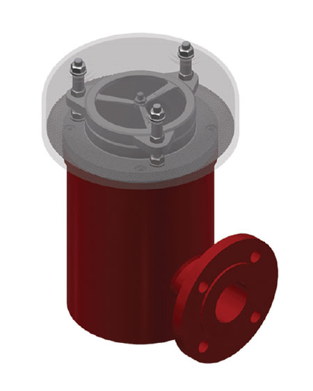
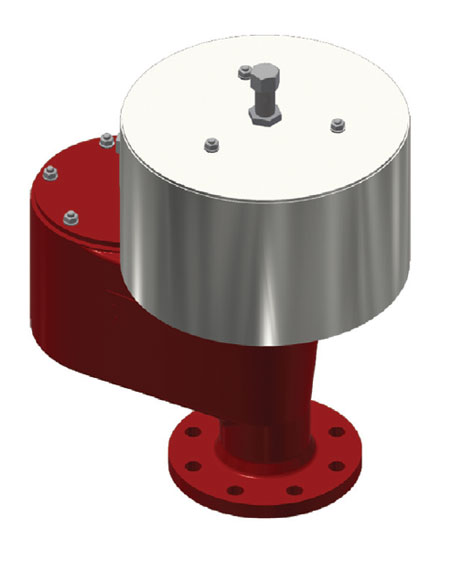
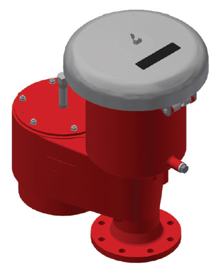
Various valve disk technologies
Apart from overpressurisation, ventilation is required in the event of vacuum.
A vacuum can be caused by pumps, emptying a tank, by thermal influences that cool the tank down (e.g. during thunderstorms), by extremely high leakage volumes (e.g. cracks in the pipe), by condensation or by an increase in atmospheric pressure. Once the required performance has been determined, it is necessary to determine the set pressure (the positive or negative pressure that is noted on the name plate) of the breather valve.
At this point, various valve disk technologies must be considered. We differentiate between the full lift plate, which requires a pressure increase of less than 10 per cent, and the proportional plate, which requires a pressure increase of 40 to 100 per cent.
Closing pressure
The full lift plate will therefore reach its full stroke (increase in pressure after the response until the required nominal capacity is reached) after a pressure increase of 10 per cent above the opening pressure (the set pressure plus the manufacturer’s tolerance at 0 bar back pressure, thus a balance of forces). The proportional plate will reach its full stroke at 40 to 100 per cent above the set pressure. However, it is also important to note the closing pressure (the valve is closed and sealed again) of the valve.
An optimized and qualitatively “better” valve, which basically requires the lowest possible pressure increase (10 – 40 per cent) and at the same time can provide an early (90 – 95 per cent) closing pressure or blow down, reduces the emissions to a minimum and reduces the probability of the occurrence of dangerous explosives atmosphere and thus contributes to the safety of the system.
Basic distinction
It is important to note that tank pressures are handled differently depending on the tank construction standard applied. The API design uses the MAWP (maximum allowable working pressure) which may then also be exceeded for the purposes of (emergency) ventilation.
Once the set pressure has been determined, the correct valve must be selected. The challenge is that manufacturers have differ-ent types of valves with different nominal diameters. Experience is required here to determine the right valve for the respective application.
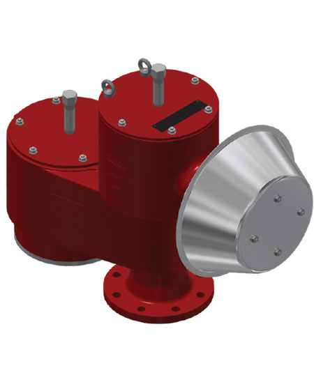
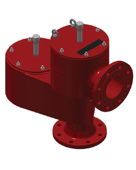
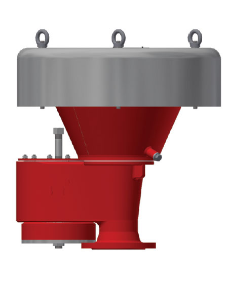
With a certain nominal size, some valves only provide small flow rates and are inexpensive, while others have very large flow rates with the same nominal size and are therefore more expensive. The location of installation and type of valve must also be determined. A basic distinction is made between end-of-line valves and in-line valves, which in turn can be designed as overpressure, vacuum or combined overpressure and vacuum breather valves.
Sealing type
The type of protective function must also be taken into account, so it is necessary to determine whether additional requirements such as protection against deflagra-tion, short-term or endurance burning are TECHNICAL in order. The requirements for integrated flame arresters are also determined by the flash point of the stored substances. If the flash point of a substance is < 55 °C, one speaks of so-called flammable substances and the usage of flame arresters is required. Further criteria for the use of flame arresters can be found in the applicable standards, e.g. TRGS 723/724, 2014/34/EU, CEN/TR 16793 or DIN SPEC 26056.
The standards relating to the calculation of the respiratory performance are not decisive at this point. The type of sealing applicable to the valve pallet is another criterium that has to be taken into consideration when designing the valve. A distinction is made here between soft sealing (e.g. Perbunan or PTFE) and metal seal-ing. The better the seal, the lower the possible leak rates below the set pressure.
Valves pallets with metal seal have the lowest possible leakage rate. It should be noted that the leak rate requirements set by ISO28300/API2000 are only minimum requirements. It should be every operator’s goal to use valves that have the lowest leakage rates. With regard to the VOC emission protection decision, the “Path to Net Zero” will become increasingly relevant in the coming years.
Weight-loaded or spring-loaded
Depending on the set pressure, the valves are either weight-loaded or spring-loaded. The advantage of the weight-loaded valves is that even the lowest pressures (from a set pressure of 1 mbar) can be achieved. The weight-loaded valves become problematic at higher set pressures (this depends on the design and nominal size of the valve) due to the high-load weight required.
With large tanks in particular, weight-loaded valves quickly exceed the tank’s maximum roof load. To save weight, spring-loaded valves are used, in which case the counterforce is no longer provided by a weight but by a spring. Spring-loaded valves are always preferred for higher pressures (from approx. 100 mbar) set pressure.
Material selection
Another option to consider when choosing a breather valve is the material. To be resistant to the processed product, materials such as steel and stainless steel, but also plastics such as polypropylene or polyethylene are selected. High-alloy materials such as Hastelloy® are also not uncommon.
In some cases, it also makes sense to coat the valves from the inside. For example, an ECTFE coating offers the possibility of achieving a high surface quality, which means that sticky or polymerizing substances create deposits much more slowly. Other options for valves are heating systems. Viscous or sticky sub-stances can clog the valve, which restricts its ability to function.
In a worst case scenario, this can lead to the build-up of impermissible pressures, which could damage the tank. To avoid the formation of these deposits, various technologies are used in heating systems, depending on how high the required heat input should be. You can choose between valves with a double jacket (for steam or hot water heating) or electric heating, including thermal insulation and cladding. Of course, the heating systems must also meet the relevant ATEX requirements if the operator has declared an ATEX zone.
If the stored substance contains large amounts of water (e.g. biogas), then the use of a condensate drains should also be discussed. Here, the condensate can be discharged, for example, on the side of or below the valve. This reduces the risk that the condensate freezes inside of the valve, especially in cold regions, and the valve can no longer open.
About the author:
Martin Hundt is Associate Sales Director at HUCKAUF INGENIEURE GmbH. His passion lies with safety devices such as flame arresters, valves or rupture discs. The topic of plant safety with the focus on mechanical explosion protection and pressure relief systems has always been an essential part of his work. KITO Armaturen GmbH – martin.hundt@huckauf


