Flange leaks can mean lost productivity, safety hazards, and expensive repairs. Learn how to prevent these issues with proper training and techniques.
By Sandy Van den Broeck, Director Product Management and Strategic Projects at Burgmann Packings Group GmbH and member of ESA – Flange Gasket Division
A study by the Pressure Vessel Research Council (PVRC) in the USA found that most flange joint leaks stem from:
- Improper installation (26%)
- Flange damage (25%)
- Gasket issues (22%)
- Loose bolts (15%)
- Flange misalignment (12%)
While this isn’t an exhaustive list, addressing these factors highlights the importance of comprehensive technical training for personnel involved in flange assembly.
Choosing the right materials
Selecting the correct materials for the application is crucial. All components of the flange assembly, from the bolts and gasket to the flange itself, must be compatible with each other and able to withstand the operating conditions they’ll encounter. Insufficient bolt load can occur due to several factors: incorrect initial torque, damaged bolt threads, vibrations causing self-loosening, or neglecting to use lubricant (the most common on-site mistake). Conversely, applying excessive bolt loads can bend flanges, crush gaskets, or even permanently stretch the bolts beyond their elastic limit. The type of washer used (soft versus through-hardened) significantly impacts the residual bolt load.
Flange leaks
While gaskets are the least expensive component in a flanged connection, improper selection or installation can turn them into the most costly element. Choosing the wrong material for the media, pressure, or temperature, using the incorrect size or thickness, or reusing or greasing a gasket can all lead to leaks. Additionally, bending the gasket due to external forces, retightening it at high temperatures, or allowing it to become brittle can compromise its effectiveness.
Similarly, improper flange preparation can spell disaster. Flange surfaces with excessive damage, warping, misalignment, or the wrong material selection will lead to joint failure. Failing to clean the flange surfaces beforehand further increases the risk of leaks. Incorrect torque calculations, poor tightening and installation procedures, or using the wrong or uncalibrated torque tools can all contribute to premature joint failure. Don’t be tempted to cut corners by using low-cost materials or employing personnel who haven’t received proper training for flange assembly.
Regulation and training
In the EU, the qualification of personnel competency in the assembly of the bolted connections of critical service pressurized systems is regulated by the EN1591-4 and in the US, bolting specialist qualification program’s courses are derived from the ASME PCC-1 Appendix A “Guidelines for Pressure Boundary Bolted Joint Assembly Personnel.”
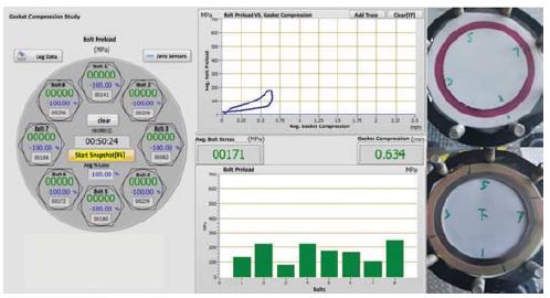
By using a state-of-the-art Flange Assembly Demonstration Unit and associated instructional training, enables on-site technicians in Refineries, Petro-Chemical plants, Power generation and general industries to better understanding gasket joint behaviour, assembly considerations and improving the quality of bolted flange assembly techniques. The hands-on training is performed by using a flanged rig which consists of a standard 4” 150 Lbs – 8 bolted flange connection and presents in real time via a digital display the individual bolt stress, the average bolt stress as well as a bar graph to demonstrate the scatter in pre-load and gasket load-deflection curve.
We will demonstrate the impact of improper bolt tightening procedure and the effect of non-lubricating bolts and load bearing surfaces during the installation of a spiral wound gasket. The effects of lubrication on the stud and nut does have a significant impact on the gasket load behaviour can be demonstrated as well as the usage of steel hardened washers and correct tightening procedure, as shown in the next test simulations.
Simulation test 1
Gasket: Spiral Wound Gasket graphite filled without inner ring 4” 150Lbs- ASME B16.20., without using steel-hardened washers and no lubrication and non-appropriate tightening procedure, full torque setting in clockwise sequence.
In this test we make use of a SWG without inner ring, simulating the described, as mentioned above. The flange on the left side shows the load per bolt (green value). The graph on top right shows the relation between the average bolt stress (in MPa) and its compression (in mm) and the block diagram shows the bolt load distribution.The lack of lubrication of threads,load bearing surfaces and absence of washers, results in insufficient bolt load and gasket compression.
The improper bolt tightening procedure – using full torque in a clock wise sequence – results in an uneven bolt load distribution. Top far right picture shows the impression of the gasket on a pre scale Fuji film. In first view from this picture one couldn´t see the insufficient gasket compression or distribution, because of the soft graphite which comes in first contact with the pre scale film.
The pre scale clearly shows the inward deformation of the spiral, which is called “buckling.” At elevated pressures, this could result in breaking the spotwelds, leading to damage of pumps and valves in the pipeline. Therefore, SWG with inner rings are preferred to avoid inward deformation, preventing damage to the system.
Simulation test 2
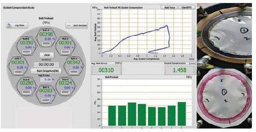
In this test we will still use the SWG without inner ring, however we will now apply the best installation practice, by using lubricated bolts, steel hardened washers and correct tightening procedure.
The load distribution still varies even after applying full torque in a cross wise manner. This is due to the typical behaviour of a SWG, the gasket will set under compressive load. Therefor and often neglected is to carry out a final step, which means to apply full torque, clockwise from bolt 1 to bolt 8 until zero movement of the bolts. This is important to flatten out the variation and generates a more even bolt load distribution.
It is clearly visible that due to lubrication, steel hardened washers and correct tightening procedure the bolts have received a higher and even bolt load distribution. On the other hand, one can see clearly now the impact of the higher bolt load resulting in a higher gasket compression. Gasket deformation or “buckling” towards the inside is more visible now.
Conclusion: For higher pressures above 300Lbs and SWG fitted with PTFE filler material the preference is to use a SWG with an inner ring.
Simulation Test 3
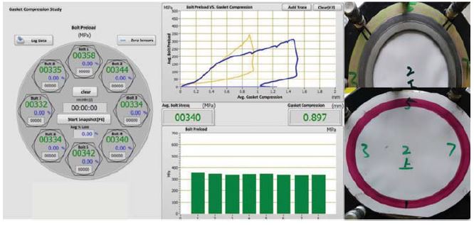
For this test simulation we will now use a SWG with an inner and outer ring to show the difference compared to the previous test. We will use the correct crosswise tightening procedure including lubricated bolts and steel hardened washers. Compression is at its maximum and limited now by both external and internal ring.
Due to the behavior and setting of the SWG even at the last step where full torque has been applied, crosswise, it still shows some slight variation in the bolt load distribution. However, this variation is completely equalized after the last step, tightening all bolts at full torque in clockwise direction, until zero nut movement. The block diagram now shows a perfect bolt load distribution, also improved by the presence of the inner ring.
For gasket compression and unloading on the graph one can clearly see the difference between the two tests. The presence of an inner ring prevents inward deformation and reduces the risk of damaging the equipment further down the pipeline.
Summary: Proper installation practices, including the use of fully trained personnel and controlled tightening methods, guarantee the reliability and safety of flange connections.
About the author
 Sandy van den Broeck is Director Product Management and Strategic Projects at Burgmann Packings Group GmbH and a member of the ESA Flange Gasket Division.
About this Technical Story
This Technical Story is an article from our Valve World Magazine, April 2024 issue. To read other featured stories and many more articles, subscribe to our print magazine. Available in both print and digital formats. DIGITAL MAGAZINE SUBSCRIPTIONS ARE NOW FREE.
“Every week we share a new Technical Story with our Valve World community. Join us and let’s share your Technical Story on Valve World online and in print.”
